

In the highly constrained environment of a closed aquatic ecosystem, strict thermal stability dictates the survival of all biological organisms. Unlike the open ocean, which possesses massive thermal inertia, a home aquarium is highly vulnerable to rapid temperature fluctuations and hardware-induced energy spikes. As a heating element drives the water temperature upward, the water’s capacity to hold dissolved oxygen diminishes rapidly, making active dissolved oxygen telemetry critical during heat spikes. Simultaneously, the metabolic rate of your livestock accelerates, drastically increasing their biological oxygen demand. This creates a fatal physiological intersection: livestock will succumb to hypoxia long before they experience direct thermal denaturing of their cellular proteins.
Historically, the single largest point of failure leading to this exact catastrophe is the standard submersible aquarium heater. The internal bimetallic thermostat within these devices frequently arcs and welds shut over thousands of operational cycles. Consequently, preventing aquarium heater stuck on failure requires completely isolating the heating element from the delicate logic required to control it.
However, simply plugging a heater into a basic external thermostat is an incomplete solution. True security demands layered, autonomous architectural failsafes, a concept known as aquarium heater controller redundancy. Building a robust thermal defense begins with a dual stage temperature controller aquarium setup, ensuring the environment is bracketed against both extreme drops and severe spikes.
In this comprehensive engineering guide, we will systematically rectify the gaps in mainstream aquatic thermal management. We will analyze the structural integrity differences in the ongoing inkbird vs ranco aquarium temperature probe debate, and expose the unseen dangers of ntc thermistor temperature drift that silently corrupts baseline data over time. Furthermore, we will break down dangerous solid state relay failure modes, establish mathematically safe protocols for titanium heating element grounding, and integrate advanced IoT thermal alarm telemetry so you are instantly notified the moment your hardware begins to fail.
Table of Contents
Gap Analysis: Mainstream Misconceptions in Aquatic Thermal Management
An exhaustive review of aquatic platforms, hobbyist forums, and consumer hardware manuals reveals a profound lack of technical depth regarding advanced thermal regulation. Mainstream advice heavily promotes acquiring an external thermostat as a complete cure-all for aquarium heater failure. While stepping away from reliance on fragile bimetallic strips is a necessary evolution, the prevailing literature critically underrepresents the sophisticated failure modes of the external units themselves.
Achieving true biosecurity requires moving beyond basic single-device setups toward engineered aquarium heater controller redundancy. Relying on surface-level hobbyist tips leaves critical vulnerabilities unaddressed across semiconductor physics, metrology, and electrical grounding.
Critical Gaps in Conventional Thermal Management
- Overlooking Solid State Relay Failure Modes: Throughout popular DIY forums and commercial marketing, SSRs are heralded as the ultimate upgrade over electromechanical relays due to their silent switching and theoretically infinite lifespan. This optimistic assessment ignores the core physics of semiconductor devices. When subjected to thermal breakdown or inductive overvoltage transients, an SSR will almost exclusively fail in a closed, short-circuited state. Without redundant cutoff contactors, an aquarist simply moves the risk of a heater stuck on failure from a submerged glass tube to an external wall-mounted box, leaving livestock fully vulnerable to thermal runaway.
- Ignoring NTC Thermistor Temperature Drift: Consumer guides focus intensely on out-of-the-box probe precision, debating fractions of a degree. However, they uniformly ignore long-term ntc thermistor temperature drift and the physical degradation modeled by the Steinhart-Hart equation. Over continuous months of submersion, moisture permeation and thermal cycling alter the crystalline structure of the sensor’s sintered metal oxides, introducing silent calibration shifts. Without systematic calibration against NIST-traceable standards, the controller calculates duty cycles using corrupted baseline telemetry.
- Misunderstanding Titanium Heating Element Grounding: The discourse surrounding stray voltage in the water column remains dangerously fragmented. Hobbyists frequently install standalone grounding probes to eliminate mild static tingles, treating all electrical potential identically. This simplistic practice fails to distinguish between capacitive coupling (harmless induced voltage) and galvanic leakage (lethal fault voltage). Deploying a conductive titanium heater ground without pairing it directly with Ground Fault Circuit Interrupter (GFCI) architecture creates a low-resistance path that sustains continuous fault current, turning the aquarium into an electrocution hazard.
Addressing these three systemic blind spots forms the foundation of a resilient thermal management strategy, combining multi-stage logic with fail-safe electrical architecture.
Structural Engineering of Aquarium Heater Controller Redundancy
To achieve absolute biosecurity, an aquatic thermal system must be engineered under the operational reality that every electrical and mechanical component will eventually fail. Industrial aquarium heater controller redundancy relies on a layered topology encompassing mechanical wattage limitations, electrical series interlocks, and autonomous logic gates. The engineering objective is to isolate and neutralize a localized component failure before it triggers an environmental catastrophe.
Distributed Thermal Capacity
A frequent architectural vulnerability in aquarium design is relying on a single, oversized heating element to stabilize the entire water volume. For example, maintaining a 150-gallon system with a single 600-watt heater introduces high systemic vulnerability: if the controlling relay welds closed, 600 watts of continuous thermal dissipation will rapidly overwhelm the water mass and destroy the tank within hours.
- Splitting the Thermal Load: Instead of a single high-wattage element, distribute the load across three independent 200-watt heaters.
- Passive Dissipation Balancing: If an individual 200-watt element suffers a closed-circuit failure, its isolated thermal output cannot rapidly elevate the temperature of a 150-gallon volume. The passive heat loss from the tank to ambient room air largely neutralizes the rogue output, expanding the intervention window from minutes to days.
The Hybrid Failsafe: Internal and External Thermostat Calibration
When integrating an external digital unit into your dual stage temperature controller aquarium setup, never disable or bypass the internal bimetallic thermostat of an adjustable heating element. Instead, repurpose it as a mechanical hardware high-limit interlock.
- Calibration Offset: Configure the external digital unit as the primary logic gate to handle day-to-day switching cycles, and set the internal bimetallic dial exactly 2°F to 3°F higher than your controller’s target threshold.
- Mechanical Isolation: Under regular operations, the internal bimetallic contacts remain continuously shut without generating mechanical arcing or carbon pitting.
- Thermal Runaway Cutoff: If the upstream digital relay suffers a catastrophic short and continues feeding power, the rising water temperature will hit the internal bimetallic limit. The bimetallic strip bends away from the contact, mechanically severing the circuit and terminating thermal runaway autonomously.
Series Circuit Relay Redundancy
Commercial and industrial facilities eliminate single points of failure by wiring dual relays in an electrical series configuration. Current must traverse both switches concurrently to energize the heating element.
- Primary Logic Switch (Relay A): A solid-state relay (SSR) manages high-frequency proportional-integral-derivative (PID) micro-cycling to maintain tight thermal bands.
- Secondary Cutoff Contactor (Relay B): A heavy-duty electromechanical contactor sits downstream in the series loop, remaining open only during standard operation.
- Microcontroller Fault Detection: If the logic board detects temperature exceeding the high alarm threshold while Relay A is commanded “OFF”, it identifies a shorted semiconductor junction. The controller immediately de-energizes Relay B, cutting mains power to the heater and fully mitigating a stuck-on disaster.
Optimizing the Dual Stage Temperature Controller Aquarium Setup
A resilient thermal management architecture requires bidirectional environmental control. A single-stage thermostat can only inject heat into the water column, leaving the ecosystem completely vulnerable to thermal accumulation driven by high ambient room temperatures, high-output lighting systems, and submersible pump motor heat. A comprehensive dual stage temperature controller aquarium setup resolves this vulnerability by operating independent heating and cooling circuits, maintaining a tightly bracketed thermal corridor.
In this dual-stage architecture, the controller continuously samples telemetry from the temperature probe and routes power dynamically:
- Heating Stage: Energizes submersible heaters or titanium elements if the water temperature breaches the lower setpoint.
- Cooling Stage: Energizes evaporative fan arrays, thermoelectric Peltier chillers, or refrigerant compressors if water temperature breaches the upper setpoint.
The Role of Hysteresis and Deadband Calibration
The critical parameter in any dual-stage installation is hysteresis, commonly designated as the switching differential or deadband. Hysteresis defines the mandatory operational gap between the engagement setpoint and the disengagement setpoint of an individual relay.
Attempting to enforce an absolute, static setpoint (such as exactly 78.0°F) forces the logic board into high-frequency cycling, a destructive state known as relay chatter:
- Mechanical Relay Degradation: Rapid micro-toggling induces continuous electrical arcing across copper contacts, degrading the conductive pads and dramatically increasing the probability of contact welding.
- Compressor Motor Destruction: For refrigerant chillers, cycling power without sufficient resting duration prevents internal refrigerant pressures from equalizing, causing immediate compressor stall or winding burnout.
- Deadband Buffer Zone: Maintaining an adjustable hysteresis between 0.5°F and 1.0°F prevents hardware fatigue while remaining biologically imperceptible to sensitive livestock.
| Control Parameter | Temperature Threshold | Relay Status & System Action |
|---|---|---|
| Cooling Upper Limit | 79.0°F | Cooling Relay CLOSED (Chiller/Fans ON) |
| Cooling Hysteresis Target | 78.5°F | Cooling Relay OPENS (Chiller/Fans OFF) |
| System Deadband (Idle) | 78.0°F – 78.5°F | All Relays OPEN (System Idle, 0W Thermal Load) |
| Heating Hysteresis Target | 78.0°F | Heating Relay OPENS (Heater OFF) |
| Heating Lower Limit | 77.5°F | Heating Relay CLOSED (Heater ON) |
This structured 1.5°F operational envelope optimizes hardware longevity by establishing extended rest intervals between duty cycles, maximizing the Mean Time Between Failures (MTBF) for both heating and cooling units.
Preventing Aquarium Heater Stuck on Failure: Solid State Relay Failure Modes
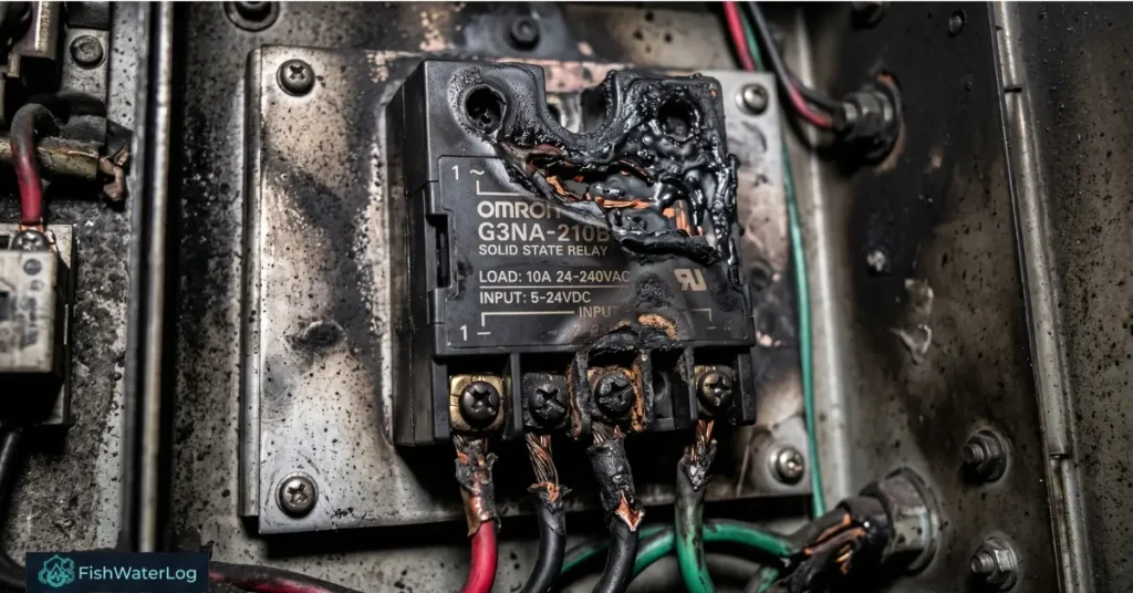
Beyond electronic controllers, true physical redundancy requires the ‘Split Wattage’ rule. Instead of utilizing a single high-wattage heating element (e.g., 300W), divide the total required wattage across two undersized heaters (e.g., two 150W units). If a catastrophic controller short occurs and locks one heater in the ‘ON’ position, a single undersized element lacks the thermodynamic output to boil the aquarium, granting the operator critical time to intervene.
Advanced DIY controllers—such as systems built on the Reef-Pi architecture or custom Arduino microcontrollers—rely heavily on Solid State Relays (SSRs) instead of traditional electromechanical relays (EMRs). SSRs utilize internal optocouplers to galvanically isolate low-voltage logic from high-voltage AC line power, using triacs or silicon-controlled rectifiers (thyristors) to switch the load silently and without physical contacts.
However, successfully preventing aquarium heater stuck on failure demands an understanding of semiconductor breakdown physics. While an electromechanical relay can fail in either an open or closed state depending on spring fatigue and arcing, an SSR undergoing physical degradation fails almost exclusively in a closed, short-circuited state. When this happens, full line voltage continues to energize the heating element indefinitely, irrespective of logic commands.
Thermal Breakdown Mechanics and Junction Saturation
Unlike copper mechanical contacts that exhibit nominal resistance when closed, a semiconductor junction maintains an inherent forward voltage drop between 1.2V and 1.6V during conduction. According to Ohm’s and Joule’s laws of power dissipation P = I × V, an SSR conducting a 15-ampere load will continuously shed approximately 20W to 24W of waste heat directly within its encapsulated package.
- The Arrhenius Law: In semiconductor physics, operating temperatures dictate component longevity; every 10°C rise in junction temperature cuts the operational lifespan of the thyristor in half.
- Thermal Avalanche: Once internal junction temperatures exceed operational limits (typically 80°C to 115°C depending on silicon doping), the semiconductor loses its gate-blocking capability. The silicon lattice breaks down, welding into a continuous conductor and locking the heater in an unyielding “ON” state.
- Heat Sink Integration: For an exhaustive breakdown of how inadequate heat sinks cause thyristor degradation, consult this technical documentation on frequent thermal design errors with solid-state relays.
- Aggressive Thermal Derating: Never run an SSR near its rated nameplate capacity. For a 300-watt aquarium heater drawing approximately 2.5A at 120V AC, avoid generic 5A modules; deploy a 25A or 40A industrial-rated SSR secured to an extruded aluminum finned heat sink with high-conductivity thermal interface material (TIM).
Overvoltage Breakdown and Inductive Line Transients
While pure resistive loads like heating elements do not generate magnetic kickback, aquarium control panels frequently share branch circuits with heavy inductive equipment, including variable-speed DC pumps, large AC return pumps, and protein skimmers.
- Back EMF Induction: When large inductive AC motor windings disengage, their collapsing magnetic field induces high-voltage spikes (back electromotive force, or Back EMF) that propagate across line power.
- Reverse Avalanche Destruction: If a line spike exceeds the peak non-repetitive reverse blocking voltage of the thyristor (for example, an 800V transient striking an SSR rated for 400V to 600V), reverse avalanche breakdown shatters the internal barriers, shorting the terminals permanently.
- Transient Surge Mitigation: Install a Metal Oxide Varistor (MOV) wired in parallel directly across the AC load terminals of the SSR. The MOV exhibits megaohm-level resistance during nominal 120V/240V sine wave operation, but drops its impedance instantaneously during high-voltage surges, diverting damaging transients safely around the thyristor.
| SSR Failure Mode | Primary Root Cause | Physics of Failure | Engineering Mitigation Strategy |
|---|---|---|---|
| Thermal Breakdown | Sustained high current; undersized heat sink | Thyristor junction temperature exceeds silicon barrier limits, fusing closed. | Derate capacity by 300%; mount to finned aluminum heat sink using thermal paste. |
| Overvoltage Breakdown | Inductive back-EMF spikes from pump motors | Voltage spike breaches peak reverse blocking voltage threshold. | Wire a high-energy Metal Oxide Varistor (MOV) in parallel across output terminals. |
| Overcurrent (Surge) | Internal element insulation breakdown or short circuit | Instantaneous current spike vaporizes internal silicon bonding wires. | Install an ultra-fast acting, semiconductor-grade fuse rated directly to load current. |
| Leakage Current | Natural semiconductor barrier bleed | Minor milliamp leakage current passes through even while commanded "OFF". | Wire a secondary mechanical relay or contactor in series for absolute galvanic isolation. |
Inkbird vs Ranco Aquarium Temperature Probe: Architectural Integrity
When moving away from hobby-grade internal thermostats, commercial controller selections center on two divergent engineering philosophies: consumer-focused precision versus industrial-grade resilience. This division is exemplified in the ongoing debate surrounding the inkbird vs ranco aquarium temperature probe architecture. Understanding the physical construction of each unit is essential for designing a multi-layered fail-safe system.
The Ranco ETC-111000: Industrial Durability
Ranco temperature controllers are engineered for commercial HVAC installations, cold-storage facilities, and high-load industrial machinery. Their internal topography prioritizes mechanical endurance over aesthetic appeal or micro-precision:
- Heavy-Duty Electromechanical Contactors: Ranco controllers incorporate massive mechanical contactors engineered to switch high inductive and resistive loads repeatedly without pitting. The wide physical gap between open contacts offers substantial resistance to electrical arcing and contact welding.
- Hardware Fail-Safe Default: If a catastrophic internal circuit board or logic processor fault occurs within a Ranco unit, the mechanical contactor defaults to an OPEN (de-energized) state. This design prevents catastrophic runaway heating by cutting line power.
- Industrial Thermoplastic Probe: The Ranco probe consists of an industrial-grade thermistor sealed within a heavy, chemical-resistant thermoplastic sheath. It handles mechanical impacts and corrosive chemicals without physical degradation.
- System Limitations: The tightest programmable hysteresis on standard Ranco hardware is 1.0°F. While safe for large water bodies, this variance causes wider thermal oscillations than sensitive coral ecosystems prefer. Furthermore, Ranco units lack built-in Wi-Fi, application telemetry, and remote notification capabilities.
The Inkbird ITC-306A/308 Series: Consumer Precision and Telemetry
Inkbird controllers are widely deployed in the aquatic community due to their accessible price point, native dual-stage heating and cooling ports, and fine-tuned logic settings:
- Micro-Precision Calibration: Inkbird firmware allows aquarists to dial hysteresis down to 0.1°C (or 0.5°F), preventing noticeable thermal swings in compact or low-volume systems.
- PCB-Mounted Relays: Inkbird controllers use compact, board-mounted miniature electromechanical relays. While rated for normal heating element loads, smaller relay pads generate higher localized heat during switching cycles, making them statistically more vulnerable to welding shut than industrial contactors.
- The Probe Submersion Failure Mode: Standard Inkbird configurations often ship with general-purpose probes designed for atmospheric, homebrewing, or terrarium monitoring. When submerged long-term in an aquarium, saltwater or water pressure penetrates the molded junction between the lead wire and the metal tip. Once moisture reaches the internal thermistor, resistance drops sharply, the controller registers a false low temperature, and it engages the heating element continuously.
- Mandatory Hardware Selection: Aquarists utilizing Inkbird units must specify the dedicated “Aquarium” hardware iteration, which utilizes dual, fully potted, titanium-encapsulated probes engineered for continuous deep submersion.
The Hybrid Redundancy Architecture
To resolve the trade-offs between industrial endurance and modern precision, advanced installations combine both systems into an electrical series arrangement:
- The Primary Precision Controller: An Inkbird dual-stage controller is configured to manage daily operation with a tight 0.5°F hysteresis while handling local Wi-Fi telemetry and alarm notifications.
- The Secondary Industrial Cutoff: The Inkbird is plugged directly into the output receptacle of a Ranco ETC-111000. The Ranco’s upper cutoff limit is configured as an emergency boundary set to 82.0°F.
- Fail-Safe Operation: Under standard conditions, the Ranco contactor remains closed, allowing the Inkbird to regulate thermal bands. If the Inkbird’s internal PCB relay welds shut, water temperature rises to 82.0°F, at which point the Ranco opens its heavy contactor, cutting mains power to the runaway heater and protecting the ecosystem.
Ensure secondary sensors are secured in a high-flow chamber within your freshwater sump overflow system to avoid localized thermal stratification.
NTC Thermistor Temperature Drift: Metrology and Mitigation
The operational accuracy of an aquarium heater controller redundancy architecture—regardless of relay quality or logic complexity—depends entirely on the telemetry delivered by its temperature sensor. The vast majority of digital units, spanning commercial off-the-shelf devices and custom automation microcontrollers, utilize Negative Temperature Coefficient (NTC) thermistors to monitor ambient water conditions.
NTC thermistors are ceramic semiconductor resistors manufactured from sintered metal oxides. Their fundamental electrical property is an inverse relationship between thermal energy and resistance: as ambient water temperature increases, the sensor’s electrical resistance predictably declines. Long-term continuous submersion exposes these sensors to ntc thermistor temperature drift—a slow, physical alteration in baseline semiconductor resistance that silently corrupts operational accuracy over time.
Furthermore, external biofouling accelerates false readings. Calcium carbonate precipitation and thick bacterial biofilms act as powerful thermal insulators over the probe’s titanium tip, creating a lag in temperature detection. Temperature probes must be routinely cleaned with citric acid and strictly mounted upstream of the heating element in a high-flow chamber to prevent localized heat looping.
The Steinhart-Hart Equation and Resistance Modeling
The relationship between resistance and temperature across an NTC thermistor is non-linear, forming a steep exponential curve. Microcontrollers convert raw resistance readings into accurate temperature values using the third-order Steinhart-Hart equation:
1/T = A0 + A1 ln(R) + A3 (ln(R))^3
- Variables Defined: T represents the absolute thermodynamic temperature in Kelvin, R is the measured electrical resistance across the probe in Ohms, and A0, A1, and A3 are fixed calibration coefficients established by the manufacturer during ceramic sintering.
- Algorithmic Disconnect: The controller’s firmware assumes these mathematical coefficients remain static throughout the lifetime of the device. When physical wear alters the thermistor’s baseline resistance (R), the equation processes flawed inputs. The controller calculates duty cycles based on corrupted telemetry, creating an unseen failure point where heating elements remain engaged even as the water column exceeds safe thresholds.
- Metrological Verification: Metrologists studying the long-term mathematical stability of sensor resistance can review the comprehensive NIST publication on NTC thermistor drift.
Physical Origins of Sensor Drift
- Microscopic Moisture Permeation: Submerged probe encapsulations frequently rely on epoxy resin fills. Under continuous hydrostatic pressure, water molecules permeate the microscopic porosity of the resin matrix. When moisture reaches the internal semiconductor elements, it forms parallel conductive channels, lowering the measured resistance and tricking the controller into registering a false low temperature.
- Lattice Strain and Thermal Aging: Continuous cycling between operational temperatures generates thermal fatigue across the polycrystalline matrix of the sintered oxides. Over extended operational windows, mechanical relaxation of the crystalline lattice shifts the zero-power nominal resistance upward or downward, compounding reading discrepancies.
Metrological Mitigation and Calibration Routines
Deploying an unmonitored probe undermines systemic fail-safe engineering. Safeguarding an ecosystem against drift requires strict mechanical encapsulation and routine physical verification:
- Hermetic Encapsulation Upgrades: Standard epoxy-coated sensors exhibit drift rates reaching up to 0.2°C per year under continuous aquatic submersion. To maintain stable telemetry, specify hermetically sealed, glass-passivated NTC thermistors housed within seamless grade-2 titanium or 316L stainless steel wells, reducing baseline drift down to approximately 0.02°C per year.
- Semi-Annual NIST Calibration Protocol: Every six months, evaluate the probe against a calibrated, NIST-traceable reference thermometer. When discrepancies appear, leverage the controller’s internal calibration offset firmware to apply a software correction, realigning the digital display with actual conditions until the sensor assembly is physically replaced.
- Biological Sensitivity: In high-precision setups, maintaining tight thermal boundaries is as critical to avoiding rhizome rot and system collapse as following a targeted Anubias nana care guide.
Titanium Heating Element Grounding: Induced Voltage vs. Fault Current
One of the most debated and misunderstood electrical safety topics in advanced aquatic design is the role of titanium heating element grounding and its interaction with stray voltage. Commercial titanium heaters are favored by serious aquarists due to their rapid thermal transfer properties, physical impact resistance, and immunity to corrosive degradation. However, because the exterior casing consists of conductive metal, it interacts with an aquarium’s electrical environment in a manner entirely distinct from standard glass or quartz tubes.
Safely engineering a redundant thermal setup requires drawing a clear line between two independent electrical conditions: Capacitive Coupling (Induced Voltage) and Galvanic Leakage (Fault Voltage).
Capacitive Coupling and Harmless Induced Voltage
An aquarium acts as a grounded dielectric basin surrounded by alternating current (AC) peripheral devices. High-output LED driver circuits, DC motor power supplies, and magnetic impellers in return pumps emit substantial electromagnetic fields.
- Electrostatic Induction: Through capacitive coupling, these ambient electromagnetic fields induce an electrostatic charge across the water column.
- Voltage vs. Current: A digital multimeter placed with one lead in the water and the second lead in an electrical earth ground will routinely measure an AC potential difference between 15V and 50V.
- Biological Impact: This reading represents electrical potential without substantial closed-loop current flow. Invertebrates and fish remain suspended safely within the equipotential field—similar to a bird perched on a high-voltage transmission line. An aquarist only experiences a faint tingling sensation when touching the water while barefoot on a damp concrete surface, temporarily acting as a high-resistance path to earth.
Galvanic Leakage and Catastrophic Fault Current
Galvanic leakage, by contrast, represents an immediate and lethal hardware failure. This occurs when physical insulation cracks, epoxy potting separates, or submersible seals breach, exposing raw 120V or 240V mains current directly to the water column.
- Lethal Exposure: Raw AC voltage seeking a ground path will generate high current density, paralyzing livestock and posing a severe shock hazard to operators.
- Electrolytic Metal Leaching: Unmitigated current passing through the water accelerates electrolytic corrosion, degrading copper windings and rapidly leaching toxic heavy-metal ions directly into the closed ecosystem.
The Grounding Probe Dilemma: Safe vs. Lethal Configurations
High-grade titanium heating elements are manufactured with a three-conductor power lead, where the dedicated earth ground wire is physically welded to the interior of the titanium shell. The instant the heater is submerged, its entire metallic surface area functions as an integrated grounding probe.
- The Safe Architecture (Titanium Ground + GFCI): When paired with a Ground Fault Circuit Interrupter (GFCI), any harmless induced static charge is immediately shunted to ground, pulling multimeter readings to 0V. If a motor block or cord insulation breaches, raw AC mains power strikes the grounded titanium tube, generating an immediate differential current between the hot and neutral lines. The GFCI registers this imbalance in milliseconds and trips the breaker, completely de-energizing the circuit, protecting livestock, and halting electrolytic heavy-metal poisoning.
- The Lethal Architecture (Titanium Ground WITHOUT a GFCI): Operating a grounded titanium heater or a standalone grounding probe on an unprotected outlet creates a high-risk electrical trap. If a submerged device experiences insulation failure, the raw line voltage seeks earth through the lowest available resistance: the grounded titanium tube. Without a GFCI to break the circuit, sustained fault current flows continuously through the water column, electrocuting tank inhabitants and generating violent copper electrolysis until equipment physically melts or burns.
Deploying grounded titanium hardware is essential for noise reduction and fault detection, but it must be paired with operational GFCI protection to ensure true system biosecurity. Routine verification of GFCI trip currents and earthing integrity should be integrated directly into your monthly freshwater aquarium equipment checklist.
Thermal Alarm Telemetry: IoT Integration and Failsafe Architectures
The final layer of aquarium heater controller redundancy relies on immediate operator notification and human intervention. Autonomous mechanical contactors and logic gates are engineered to isolate catastrophic hardware failures, but they cannot perform long-term system restoration. If an upstream controller successfully de-energizes a shorted heating element to stop thermal runaway, the immediate threat of boiling is neutralized. However, without active notification, the water column will steadily shed heat to the ambient room, exposing sensitive livestock to hypothermic shock over subsequent hours. Thermal alarm telemetry bridges the critical gap between automatic hardware cutoffs and active biological oversight.
Sudden thermal fluctuations create severe osmotic and physiological stress across fragile aquatic livestock, mirroring the ionic and mineral sensitivities outlined in our comprehensive cherry shrimp water parameters guide. When programming algorithmic fail-safes via platforms like Home Assistant or Neptune Apex, the critical command is the default mechanical state: Fallback OFF. In the event of a microprocessor freeze, MQTT broker disconnection, or power brownout, the system logic must default the contactors to an open, de-energized state, prioritizing hypothermia risk over a fatal boiling event.
Commercial and Cloud-Based Telemetry Systems
Modern high-performance setups rely on diverse Internet of Things (IoT) protocols to deliver continuous environmental telemetry:
- Enterprise Aquatic Controllers: Dedicated systems—such as the Neptune Apex or GHL ProfiLux—sample probe data minute-by-minute, streaming metrics to proprietary cloud portals. When programmed thresholds are breached (for example,
If Temp < 76.0 Then ON ALARM), the system issues real-time push notifications and automated SMS alerts directly to the operator’s smartphone. - Consumer Wi-Fi Modules: Dual-stage controllers such as the Inkbird ITC-306A feature embedded 2.4GHz Wi-Fi chipsets interfacing with mobile applications. These platforms allow operators to configure narrow high/low alert envelopes and receive diagnostic error codes if a probe disconnects, shorts, or experiences water ingress.
Decoupled MQTT Failsafe Topology
Relying entirely on a single controller for both physical switching and cloud alerting represents a single point of failure. If a transient power surge or moisture breach destroys the controller’s main processing unit, the device ceases switching and loses the ability to transmit an alert regarding its own hardware failure.
Industrial aquatic designs address this risk by separating the execution hardware from the telemetry monitoring grid:
- Independent Secondary Sensor: An autonomous microcontroller (such as an ESP32) outfitted with a waterproof temperature sensor is positioned directly inside the sump or display tank. This device does not control heaters or chillers; its sole function is observational data logging.
- Local Broker Integration: The secondary sensor broadcasts regular telemetry payloads via MQTT (Message Queuing Telemetry Transport) to a localized, on-premise automation hub like Home Assistant.
- Power Isolation and Redundancy: By maintaining the local home automation server and network switch on an Uninterruptible Power Supply (UPS), the telemetry loop functions even during localized mains power drops.
- Out-of-Band Notification Logic: If the independent sensor detects water temperature crossing emergency boundaries while the primary controller is silent, Home Assistant bypasses standard channels to trigger audible sirens and cellular SMS dispatch. This architecture guarantees that hardware degradation is communicated before livestock suffers irreversible physical trauma.
Conclusion
Achieving absolute thermal stability across a closed aquatic ecosystem cannot be accomplished simply by purchasing a larger, higher-wattage heating element. Thermal management is a rigorous structural challenge requiring the implementation of multi-layered aquarium heater controller redundancy. By understanding the mechanical wear and metallurgical arcing inherent to internal bimetallic switches, aquarists can transition the responsibility of thermal regulation to external, highly accurate dual stage temperature controller aquarium setup architectures.
However, this transition introduces complex semiconductor and metrological failure modes that demand deliberate engineering mitigations. Solid-state relays must be thermally derated, equipped with extruded aluminum heat sinks, and backed by mechanical contactors wired in series to ensure absolute protection against closed-circuit short failures. The NTC thermistor probes that provide baseline data must be treated as consumable components susceptible to ntc thermistor temperature drift, requiring routine NIST-traceable calibration offsets and hermetic glass passivation against moisture ingress. Furthermore, integrating grounded titanium heating elements requires mandatory pairing with GFCI infrastructure to eliminate induced electrostatic noise while safely tripping breakers during lethal galvanic fault currents. Finally, layering an independent, decoupled IoT thermal alarm telemetry network over the entire system ensures that when hardware inevitably degrades, the system alerts the operator immediately, preserving the delicate biological balance of the aquarium.
Frequently Asked Questions
What is the core principle of aquarium heater controller redundancy?
Aquarium heater controller redundancy is the practice of utilizing multiple independent physical and algorithmic fail-safes to ensure no single hardware fault can cause an aquarium to overheat or freeze. This involves distributing wattage across multiple smaller heaters, wiring solid-state and electromechanical relays in series, implementing dual-stage heating and cooling envelopes, and establishing autonomous high-limit cutoffs.
Why do Solid State Relays (SSRs) fail, and how do they cause thermal runaway?
SSRs fail primarily due to thermal breakdown from inadequate heat sinking or overvoltage transients generated by inductive AC motors like return pumps. Due to the semiconductor physics of silicon thyristors, thermal junction breakdown almost universally results in a permanent closed-circuit short, locking the heater in a continuous “ON” state. Mitigation requires oversizing the SSR capacity by 300%, utilizing finned aluminum heat sinks with thermal compound, and installing parallel Metal Oxide Varistors (MOVs).
What causes NTC thermistor temperature drift over time?
NTC drift is the progressive alteration of a sensor’s baseline electrical resistance caused by microscopic moisture permeating porous epoxy resin or mechanical relaxation of the sintered metal-oxide crystalline lattice from thermal cycling. This drift distorts the Steinhart-Hart equation variables processed by the controller’s logic, causing the device to act on false temperature readings.
In the Inkbird vs Ranco comparison, which unit offers greater reliability?
A Ranco ETC series controller provides superior industrial durability through massive electromechanical contactors that resist contact welding and default to an open-circuit state upon hardware failure. However, it is limited to a 1.0°F hysteresis and lacks native telemetry. Inkbird controllers deliver tighter precision (down to 0.1°C) and mobile telemetry, but utilize smaller PCB relays and require specialized titanium-encapsulated probes to prevent water ingress failures. Advanced systems frequently plug an Inkbird into a Ranco unit to combine precision with an industrial hard cutoff.
Do titanium heating elements introduce dangerous stray voltage into the tank?
No. High-quality titanium heaters feature an internal ground wire welded to the casing, which acts as a grounding probe to shunt harmless induced voltage out of the water column. However, if an electrical insulation breach occurs in another submerged pump, the grounded casing provides a low-resistance path for raw mains current. A grounded titanium heater must always be connected to a Ground Fault Circuit Interrupter (GFCI) outlet to instantly trip the circuit and eliminate electrocution risks.
Why is programmed hysteresis essential in temperature controllers?
Hysteresis (or deadband) creates a necessary buffer between relay activation and deactivation thresholds, preventing rapid cycling known as “relay chatter”. Setting an operational hysteresis of 0.5°F to 1.0°F protects mechanical relay contact pads from premature welding and prevents refrigerant compressor motors on chillers from stalling and burning out.

2 thoughts on “Aquarium Heater Controller Redundancy: Dual Stage Telemetry”