

For decades, aquarium hobbyists have endured the disruptive gurgling, slurping noises, and microbubble storms typical of conventional single-pipe drain systems. While marine reef keepers quickly embraced silent gravity drains, freshwater aquarists have often navigated conflicting advice that overlooks freshwater interfacial dynamics, higher surface tension, and planted tank CO2 retention. Deploying a beananimal overflow freshwater sump solves these hydraulic instabilities by combining three dedicated standpipes—a primary full siphon, an open channel, and a dry emergency bypass—to achieve complete acoustic silence alongside dual fail-safe flood security.
When comparing herbie vs beananimal architectures, the tri-pipe configuration provides a vital self-modulating open channel that effortlessly absorbs minor pump head fluctuations without manual intervention. Achieving this equilibrium requires precise submerged gate valve tuning. Proper tuning full siphon beananimal overflow plumbing relies on micro-metering the primary line so it handles roughly 90% to 95% of the total volume, leaving the secondary open channel pulling an ultra-thin, silent laminar sheet.
A critical step in preventing siphon cavitation aquarium plumbing instabilities is setting your drain line geometry correctly. Locating the gate valve low in the standpipe run preserves positive hydrostatic pressure, eliminating the localized vacuum drops, outgassing, and surging that plague high-drop installations.
Matching your drain sizing to your display’s target sump turnover flow rate ensures both reliable air purging at startup and adequate waste processing. Within the filtration basin, calculating proper freshwater sump bubble trap baffle spacing prevents microbubbles from sweeping past dividers and reaching the return pump impeller. Finally, calibrating an anti-siphon air hole siphon break on the return line protects your display against back-siphoning during power cuts, ensuring an entirely flood-proof, dead-silent setup.
For the original engineering schematics and baseline plumbing theory behind silent drains, study the official documentation on BeanAnimal’s silent and fail-safe overflow designs.
Table of Contents
Core Fluid Dynamics of the BeanAnimal Standpipe Architecture
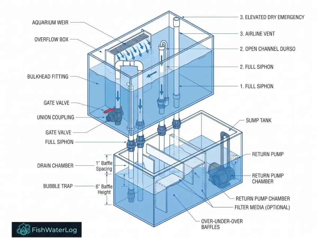
Establishing a balanced freshwater ecosystem begins with silent, reliable water movement from the display tank down to the sump. Aquarium overflow systems transport water by gravity from an elevated display aquarium down to an under-cabinet sump filter. Conventional single-pipe gravity overflows, such as standard open standpipes or vented Durso conduits, inherently mix atmospheric air with descending liquid. When the volumetric ratio of water descending a conduit exceeds approximately 25% of the pipe’s internal cross-sectional area, annular wall flow collapses into chaotic two-phase turbulence. This entrainment causes severe acoustic disturbance, erratic flow rates, and high quantities of air bubbles injected directly into the receiving sump chamber.
Implementing a beananimal overflow freshwater sump resolves this instability by partitioning gravity drainage across three distinct functional paths. When evaluating herbie vs beananimal plumbing topologies, the tri-pipe configuration provides an extra layer of dynamic buffer and fail-safe redundancy that dual-pipe systems lack. The total gravity drainage flow is distributed as follows:
Total Gravity Drainage Flow = QPrimary Siphon + QOpen Channel + QEmergency Drain
Accommodating the three independent PVC conduits of a BeanAnimal system requires significantly more linear footprint than a standard single-drain setup. For optimal surface skimming and physical fitment, implement a linear ‘Coast-to-Coast’ (C2C) internal weir or a wide external ‘Ghost Box,’ ensuring the weir spans a large percentage of the tank’s back wall.
The Tri-Pipe Operating Mechanism
Operating a silent gravity drain requires distinct hydraulic functions across each standpipe:
- Primary Full Siphon Standpipe: Fitted with a downward-facing 90-degree elbow submerged beneath the weir operating level, this line runs completely purged of air under solid fluid volume. Regulated via an ultra-fine gate valve, it transports 90% to 95% of total system circulation in dead silence. Mastering submerged gate valve tuning is essential, as executing precise tuning full siphon beananimal overflow lines locks in steady laminar throughput that matches pump delivery.
- Secondary Open Channel Standpipe: Incorporating a downward-facing intake elbow paired with an atmospheric vent airline extending above the flood line, this conduit serves as an unrestricted Durso-style regulator. It accepts the remaining 5% to 10% of surplus flow, allowing liquid to cascade down internal walls via laminar adhesion while preserving an uninterrupted central air column to eliminate aspiration noise.
- Tertiary Emergency Standpipe: Oriented upright with an open top or strainer set slightly above the operational baseline, this pipe remains dry during nominal conditions. If organic matter, detritus, or mechanical restriction blocks either working line, the weir level climbs to transform this line into a full siphon bypass, preventing catastrophic overflows. Pairing this drain with an anti-siphon air hole siphon break on the return plumbing establishes comprehensive, bi-directional flood defense during power outages.
Freshwater vs. Marine Interfacial Dynamics
While the BeanAnimal layout originated in marine setups, deploying it on freshwater sumps introduces key hydrodynamic differences:
- Elevated Interfacial Surface Tension: Pure freshwater exhibits a high surface tension of approximately 72.8 mN/m at 20 degrees Celsius, compared to saltwater’s lower tension driven by dissolved salts and surfactants. Consequently, entrained air coalesces into large bubbles rather than persistent froths, making correct freshwater sump bubble trap baffle spacing vital to prevent gas pockets from entering the return pump.
- Reduced Liquid Density: Lacking saline minerals (rho_fresh ≈ 1000 kg/m3 versus rho_marine ≈ 1025 kg/m3), pure water exhibits slightly higher discharge velocities under identical hydrostatic heads.
- Cavitation Suppression: Low-density discharge necessitates disciplined valve positioning to assist in preventing siphon cavitation aquarium plumbing failures, harmonic hunting, and surging, all while maintaining a consistent sump turnover flow rate.
Maintaining strict chemical stability across high-turnover systems requires regular monitoring, detailed further in our water chemistry telemetry directory.
Stop Losing Fish to Unknown Illnesses
Diagnose aquatic pathogens in under 60 seconds. A 2-page clinical triage flowchart and precision dosing matrix designed to treat symptoms safely without crashing your biofilter.
📥 Get Clinical Diagnostic Guide
Herbie vs BeanAnimal: Risk Engineering and Redundancy
A critical point of evaluation in aquatic hydraulic engineering is the design comparison between dual-pipe (Herbie) and tri-pipe (BeanAnimal) overflows. Both methodologies employ a throttled full siphon to suppress air entrainment; however, their risk profiles and hydraulic fault tolerances diverge substantially under real-world operating conditions.
Architectural Comparison and Fail-Safe Mechanisms
Choosing the right overflow layout directly affects daily stability, system acoustic output, and long-term flood security:
- Herbie System Dynamics: The Herbie layout relies on two conduits—a submerged full siphon throttled by a valve and an elevated emergency standpipe. To maintain silent running, the siphon must match the return pump’s delivery rate precisely, or be adjusted so an intermittent trickle enters the emergency pipe. Because it lacks an intermediate buffer, minor voltage fluctuations in return pumps, bio-slime accumulation, or line friction quickly disrupt weir equilibrium, triggering noisy splashing down the dry backup or slurping air into the main siphon.
- BeanAnimal Self-Modulating Buffer: Conversely, the BeanAnimal architecture incorporates the open channel as a self-modulating dampener. When evaluating herbie vs beananimal plumbing topologies, the primary differentiator is operational tolerance: the BeanAnimal open channel effortlessly absorbs minute discharge variations without requiring frequent gate valve adjustments. Implementing this tri-pipe configuration alongside proper tuning full siphon beananimal overflow procedures allows aquarists to dial in a set-and-forget balance, where submerged gate valve tuning keeps the siphon carrying 90% to 95% of total flow while the open channel silently handles transient fluctuations.
To explore real-world peer discussions and practical implementation logs from experienced hobbyists, you can review the community threads on Cichlid Forum.
Hydraulic Vulnerability and Flood Analysis
Drain blockage risks represent the most significant operational hazard in planted and freshwater display aquariums:
- Herbie Single-Point Vulnerability: If the primary siphon becomes obstructed by stray freshwater snails (Nerite, Pomacea) or loose plant fragments (Vallisneria, Anubias), the entire circulation volume diverts to the dry emergency standpipe instantly. If that backup pipe is undersized, partially clogged, or restricted by fittings, water levels will breach the aquarium rim within seconds.
- BeanAnimal Staged Defense: Within a beananimal overflow freshwater sump design, a primary siphon restriction first raises the weir water level, submerging the open channel’s atmospheric air-relief tube. This immediately purges the air column and converts the open channel into a second high-velocity full siphon to flush the surplus volume. The dedicated dry emergency standpipe remains untouched as an independent third-stage safeguard.
- Complete System Flood Mitigation: Matching this staged drain defense with a calibrated anti-siphon air hole siphon break on the return lines prevents siphon reverse-flow during blackouts. Maintaining a disciplined sump turnover flow rate paired with adequate freshwater sump bubble trap baffle spacing ensures the sump absorbs transient drain surges safely without entraining microbubbles into the return pump. This design also plays a direct role in preventing siphon cavitation aquarium plumbing failures by stabilizing upstream head pressures across the weir.
Submerged Gate Valve Tuning and Cavitation Mitigation
Operating a silent siphon requires maintaining equilibrium between the potential energy of the gravitational water column and the frictional resistance of the drainage conduit. In a high-performance beananimal overflow freshwater sump, balancing these gravitational and frictional dynamics eliminates surging, hunting, and pipe vibration.
The gravity siphon discharge is determined by Torricelli’s Law:
Q = CdA√2gΔhWhere:
- Q is the volumetric flow rate (m3/s).
- Cd is the coefficient of discharge (accounting for pipe friction, elbows, and valve constriction; typically 0.60 to 0.70).
- A is the pipe cross-sectional area (m2).
- g is the acceleration of gravity (9.81 m/s2).
- delta_h is the total hydraulic head differential between the weir water surface and the sump termination level (m).
Before tuning the system, ensure your assembly utilizes the correct foundational hardware to prevent air-locking and friction losses. A reliable BeanAnimal plumbing manifold requires:
- 3x Sanitary Tees: Crucial for the open channel and emergency lines to allow upward air purging; never use standard sharp 90-degree tees.
- 3x Bulkhead Fittings: Schedule 40 or 80 ABS/PVC to secure the penetrations.
- 1x True Union PVC Gate Valve: Installed exclusively on the primary full siphon line for micro-metering.
- PVC Primer & Cement: For permanent, pressure-rated solvent welds.”
Tuning Full Siphon BeanAnimal Overflow Standpipes
The process of tuning full siphon beananimal overflow plumbing relies on fine, incremental adjustments. Achieving long-term acoustic silence comes down to selecting the correct throttling hardware and understanding flow dynamics:
- Ball Valve Limitations: A primary error in aquatic installation is utilizing a standard quarter-turn PVC ball valve. Standard ball valves feature non-linear, exponential flow profiles where tiny fractions of a millimeter of rotation trigger massive changes in cross-sectional surface area. Furthermore, internal ball seats bind over time due to mineral deposits and bacterial biofilms, making micro-metering impossible.
- Precision Gate Valve Mechanics: A heavy-duty PVC or CPVC gate valve utilizes a threaded spindle that lowers a wedge-shaped gate perpendicular to the fluid flow path across multiple full rotations (1440 to 2160 degrees sweep). This linear adjustment mechanism allows fine-tuning down to a single millimeter of liquid head elevation inside the overflow weir box.
- Target Siphon Baseline: Proper submerged gate valve tuning requires stabilizing the weir level so the primary siphon transports roughly 95% of the return pump output, leaving the open channel standpipe pulling an ultra-thin laminar sheet of water down its inner walls without gurgling. Unlike the dual-pipe trade-offs evaluated in herbie vs beananimal designs, this buffer channel completely isolates your siphon adjustments from everyday pump fluctuations.
When commissioning the system for the first time, open the primary gate valve completely before engaging the return pump. Once the weir box fills and water rushes rapidly down the siphon, slowly turn the gate valve clockwise to restrict flow, stopping only when the secondary open channel carries a silent, ultra-thin trickle of water down its inner walls.
Preventing Siphon Cavitation Aquarium Plumbing Failures
In high-drop setups, siphon lines frequently suffer from violent rattling, localized hissing, and cycling water levels caused by cavitation or negative-pressure outgassing. Along any siphon conduit operating under gravity head delta_h, the local absolute internal pressure P_local is governed by Bernoulli’s energy conservation equation:
Where:
- Plocal represents local static fluid pressure.
- ρ represents freshwater density (1000 kg/m³).
- v represents flow velocity.
- z represents elevation above the reference datum.
When preventing siphon cavitation aquarium plumbing instabilities, you must prevent P_local from dropping toward the water vapor pressure (Pv ≈ 2.34 kPa at 20 degrees Celsius) or releasing dissolved gases. Key cavitation dynamics include:
- Excessive Weir Plunge Depth: If water drops more than 2 to 3 inches (50 to 75 mm) over the weir edge before striking the internal overflow water level, the kinetic impact plunges air deep into the siphon intake elbow. This entrained air collects in low-pressure zones along the pipe run, causing the siphon to fluctuate and purge rhythmically.
- Elevated Conduit Restriction: Installing a gate valve high in the standpipe assembly—immediately below the bulkhead—creates an intense localized pressure drop directly downstream of the valve plate. Atmospheric air permeates through micro-gaps in threaded fittings, or dissolved atmospheric gases strip out of solution, assembling large air bubbles that break full siphon cohesion.
- Deep Sump Discharge Submergence: Submerging the terminal end of the primary siphon more than 1 to 2 inches (25 to 50 mm) beneath the sump waterline causes hydraulic backpressure. This backpressure impedes the system’s ability to expel and purge residual air pockets during return pump startup, stalling the full siphon.
Gate Valve Elevation and Hydraulic Gradient
- Valve Placement: Position the gate valve as low as practicable in the plumbing run, directly above the sump entry bulkhead or filter sock chamber.
- Pressure Maintenance: Positioning the valve low keeps the upstream vertical PVC standpipe flooded under continuous positive hydrostatic head pressure, preventing negative pressure pockets that trigger vapor cavitation and noisy operational hunting.
- System Integration: Running an optimal sump turnover flow rate under positive pressure ensures calm, predictable drain rates. Once water enters the sump, correct freshwater sump bubble trap baffle spacing isolates any startup turbulence from the return chamber, while an anti-siphon air hole siphon break safeguards against back-siphon flooding during pump power losses.
Freshwater Sump Turnover Flow Rate and Pipe Sizing Matrix
Volumetric Flow Dynamics for Freshwater Ecosystems
In marine reef applications, target sump turnover rates are often kept moderate (3x to 5x display volume per hour), relying on in-tank powerheads and wavemakers to generate the internal laminar and turbulent shear necessary for corals. In contrast, calculating the sump turnover flow rate for freshwater systems depends directly on mechanical waste management, biological conversion speeds, and the specific fish population:
- High-Tech Planted Aquascapes: Require gentle, laminar turnover rates (2x to 4x gross volume hourly) to preserve dissolved carbon dioxide (CO2) concentrations and prevent intense mechanical outgassing across the overflow weir.
- Discus and Soft-Water Biotopes: Demand low, stable velocity turnover (3x to 5x) with zero acoustic stress to support environmental stability.
- African Cichlid (Malawi/Tanganyika) and Monster Aquariums: Require aggressive, high-flow turnover (6x to 10x display volume per hour) to process heavy organic waste, rapidly cycling suspended solids into mechanical filter fleeces or foam blocks before decomposition degrades water parameters. To select optimal mechanical pads and biological substrates to pair with your high-flow turnover rates, refer to our comprehensive best filter media guide.
When designing a robust beananimal overflow freshwater sump, matching these turnover targets with proper drain sizing ensures smooth hydraulic performance. Unlike simpler setups evaluated in herbie vs beananimal comparisons, the tri-pipe configuration handles high-flow dynamics reliably when paired with accurate submerged gate valve tuning and disciplined tuning full siphon beananimal overflow practices.
Pipe Diameter and Gravity Siphon Discharge Capacity
Undersizing drain diameters restricts flow capacity, while oversizing can make the primary siphon difficult to purge on startup, leaving residual air trapped in the line. The emergency standpipe must always be equal to, or one standard pipe size larger than, the primary siphon to safely manage 100% of return pump output during an emergency. Adhering to these structural sizing rules prevents the pressure drops that lead to preventing siphon cavitation aquarium plumbing issues, ensuring your entire fluid pathway remains balanced and quiet.
| Return Flow Target (L/h) | Return Flow Target (GPH) | Primary Siphon | Open Channel | Emergency Conduit | Application Ecosystem |
|---|---|---|---|---|---|
| 500 – 1,200 | 130 – 320 | 0.75 in (20 mm) | 0.75 in (20 mm) | 1.00 in (25 mm) | Planted Nano/Medium Aquascapes |
| 1,200 – 3,000 | 320 – 800 | 1.00 in (25 mm) | 1.00 in (25 mm) | 1.25 in (32 mm) | Community & Discus Aquaria |
| 3,000 – 6,000 | 800 – 1,600 | 1.25 in (32 mm) | 1.50 in (40 mm) | 1.50 in (40 mm) | Large Cichlid & Predatory Systems |
| 6,000 – 10,000+ | 1,600 – 2,650+ | 1.50 in (40 mm) | 2.00 in (50 mm) | 2.00 in (50 mm) | Large-Scale Monster Fish Tanks |
Freshwater Sump Bubble Trap Baffle Spacing and Microbubble Elimination
Buoyant Terminal Velocity and Stokes’ Law in Freshwater
Microbubbles swept down through drain pipes must be separated out before reaching the return pump impeller chamber. If microbubbles are drawn into the return pump, the high-shear impeller chops them into a dense cloud of microscopic bubbles that fogs the display aquarium and stresses fish gill membranes. Maintaining control over these dynamics is essential when optimizing your overall sump turnover flow rate inside a custom beananimal overflow freshwater sump setup.
The vertical migration speed of entrained bubbles is dictated by Stokes’ Law:
Where:
- vt is buoyant upward terminal velocity (m/s).
- ρliquid is freshwater density (1000 kg/m3).
- ρgas is entrained air density (1.2 kg/m3).
- g is gravity (9.81 m/s2).
- r is bubble radius (m).
- μ is dynamic viscosity of water (1.002 × 10⁻³ Pa·s at 20°C).
Because freshwater has a higher surface tension and lacks saline surfactants, entrained microbubbles rapidly coalesce into larger macrobubbles (r > 1.0 mm), yielding higher terminal buoyant velocities (vt ≈ 0.15 – 0.25 m/s). However, microscopic residual bubbles (r ≤ 50 μm) have an upward buoyant velocity of less than 0.005 m/s. Understanding these variations clarifies why structural comparisons in herbie vs beananimal engineering emphasize stable bubble management.
Hydrodynamic Sizing of Baffle Chambers
To prevent microbubbles from being pulled downward through an under-baffle, the downward linear flow velocity of water passing through the bubble trap, vfluid, must not exceed the buoyant rise velocity,
Where:
- Q is volumetric flow rate (m3/s).
- W is inner width of the glass sump chamber (m).
- S is baffle gap spacing (m).
When calculating proper freshwater sump bubble trap baffle spacing, empirical design shows that a standard baffle spacing of 1.00 to 1.50 inches (25.4 to 38.1 mm) is ideal for flow rates up to 4,500 L/h (1,200 GPH) across an 18-inch-wide sump. Ensuring correct spacing—alongside careful submerged gate valve tuning and proper tuning full siphon beananimal overflow lines—keeps the entire filtration ecosystem running quietly. Furthermore, maintaining balanced flow velocities assists in preventing siphon cavitation aquarium plumbing disruptions while working alongside safeguards like an anti-siphon air hole siphon break on the return line.
- Baffle 1 (Over): Fixes the operating water height of the biological or mechanical media chamber. Water cascades gently over this divider.
- Baffle 2 (Under): Elevated exactly 1.00 – 1.50 inches above the bottom glass panel. This forces water to pass underneath while buoyant air bubbles rise and vent at the surface.
- Baffle 3 (Over): Establishes the entry perimeter into the pump chamber, preventing laminar surface draw-down.
Spacing baffles narrower than 1 inch (< 25 mm) increases water velocity through the gap, pulling microbubbles down under Baffle 2 and directly into the return pump intake.
Failsafe Protocols: Anti-Siphon Air Hole Siphon Break and Flood Defense
Anti-Siphon Air Hole Siphon Break Calibration
When building sump plumbing for a beananimal overflow freshwater sump, protecting against reverse siphoning during a power outage is critical. When power to the return pump cuts out, the pressurized return piping instantly reverses flow, turning into a gravity siphon that pulls water backwards from the display aquarium into the sump basin. In freshwater biotopes, floating plant detritus (such as shed Vallisneria leaves) and mobile invertebrates (like Nerite snails) pose a severe risk of mechanical blockage. To defend against catastrophic clogging, the intakes of the secondary open channel and the tertiary emergency drain must be fitted with coarse PVC strainers or mesh guards to block biological debris while maintaining unhindered water flow.
To eliminate back-siphoning without relying on mechanical check valves—which are prone to jamming from algae, detritus, and snails—an anti-siphon air hole siphon break must be drilled directly into the return plumbing. Properly calibrating these safety features complements your overall sump turnover flow rate design and works alongside disciplined submerged gate valve tuning to ensure comprehensive flood prevention:
- Hole Sizing: Drill two independent 3/16 in to 1/4 in (4.5 – 6.5 mm) relief apertures in the return nozzle body. Never drill a single, pinhole-sized opening, as small holes can easily be blocked by surface tension, calcium deposits, or biofilm.
- Vertical Positioning: Situate the holes between 0.25 and 0.33 inches (6 – 8 mm) below the standard display operating waterline.
- Redundancy and Orientation: Angle one hole at 45° downward to direct water flow into the aquarium, and aim the secondary backup hole sideways. The moment a power outage lowers the display water level by only a quarter of an inch, atmospheric air rushes through the exposed holes, breaking the water column and stopping back-siphoning within seconds.
Emergency Standpipe Drainage and Sump Reservoir Headroom
Every sump must maintain adequate expansion headroom to catch water that drains down when the return pump shuts off. Total back-siphon drainage volume, V_drain, can be calculated with this volumetric formula:
Where:
- L_tank is aquarium length (cm).
- W_tank is aquarium width (cm).
- \Delta d is the total downward water travel before the anti-siphon holes break vacuum (cm).
For example, in a standard 500-liter aquarium measuring 150 cm x 60 cm, a downward travel of \Delta d = 2.5 cm (1 inch) yields:
The sump’s final return pump compartment must have enough empty air headroom above its running waterline to safely absorb this 22.5-liter surge without overflowing.
Additionally, unlike standard configurations evaluated in herbie vs beananimal risk assessments, the tertiary emergency standpipe in a BeanAnimal setup must exit above the sump waterline rather than being submerged. This ensures that if a blockage triggers the bypass—while you fine-tune your tuning full siphon beananimal overflow lines or maintain correct freshwater sump bubble trap baffle spacing—the loud splashing sound immediately alerts you that maintenance is required. Maintaining proper hydraulic gradients also assists in preventing siphon cavitation aquarium plumbing noise, securing an entirely fail-safe system.
Because the return pump compartment is the only zone where evaporation reflects, ensure stable water levels by installing an aquarium auto top off with proper sensor calibration.
Conclusion
Plumbing a beananimal overflow freshwater sump provides an effective, quiet, and fail-safe filtration system for modern aquariums. By distributing flow across a primary full siphon, an open channel buffer, and a dry emergency pipe, this system completely removes the loud gurgling and hydraulic instability common to single-drain designs.
Achieving reliable, set-and-forget performance requires adhering to key hydraulic principles:
- Use a precision multi-turn gate valve positioned low in the standpipe run.
- Maintain proper baffle spacing (1.00 to 1.50 inches) to allow microbubbles to rise and separate out naturally.
- Drill redundant anti-siphon holes to prevent back-siphoning during power cuts.
Following these engineering guidelines ensures your freshwater setup runs with complete acoustic silence and comprehensive flood protection. While an efficient sump handles suspended solids, routine substrate maintenance like learning how to clean aquarium gravel ensures total organic waste control.
Frequently Asked Questions
Why does a freshwater full siphon surge or hunt periodically?
A hunting or pulsing siphon is almost always caused by air trapped inside the standpipe. This occurs when the gate valve is positioned too high in the plumbing run, the siphon outlet is submerged too deeply in the sump (>2 inches / 50 mm), or water drops too far over the weir into the internal overflow box. Lower the gate valve closer to the sump waterline, reduce outlet submergence to 1 inch (25 mm), and raise the internal box water level to resolve surging.
Can a ball valve substitute for a gate valve on a BeanAnimal primary drain?
No. Standard ball valves rely on a quarter-turn mechanism that makes precise, millimeter-scale adjustments to the pipe’s internal cross-section nearly impossible. They also become stiff and bind over time, making it difficult to dial in the siphon without overshooting into an air-sucking or surging state. Multi-turn PVC gate valves are essential for fine-tuning siphon equilibrium.
How does freshwater surface tension alter overflow weir behavior compared to reef systems?
Freshwater has a higher interfacial surface tension (≈ 72.8 mN/m) than saltwater. Because of this, freshwater doesn’t produce persistent frothy microbubbles; instead, entrained air quickly merges into large air pockets. This requires overflow weir teeth to be wider to prevent water from backing up, and necessitates placing the gate valve low to prevent outgassing and cavitation within the siphon conduit.
How deep should the drain pipes terminate below the sump waterline?
The primary full siphon and the secondary open channel pipes should terminate exactly 1.00 inch (25 mm) below the running water surface of the sump. Submerging them deeper creates backpressure that prevents the primary pipe from purging air during pump startup. The emergency standpipe should terminate 1.00 to 2.00 inches above the waterline so that splashing water alerts the aquarist if it engages.

1 thought on “Beananimal overflow freshwater sump Guide: Siphon Tuning”