

The integration of automated hydro-mechanical systems into aquatic husbandry represents a critical evolution from manual maintenance to precise environmental control. Historically, the discourse surrounding advanced telemetry, environmental probes, and automated dosing has been overwhelmingly directed toward marine reef aquariums where salinity swings prove immediately fatal. Consequently, automated fluid management remains largely overlooked in non-marine ecosystems, presenting a significant informational gap in aquatic engineering. However, the foundational requirement for osmotic and biochemical stability applies equally across all aquatic biomes.
Implementing a meticulous aquarium auto top off setup serves as a foundational infrastructure upgrade that mitigates the primary vector of environmental instability: evaporative water loss. An Automated Top-Off (ATO) system operates as a closed-loop control mechanism engineered to monitor fluid levels within a primary display tank or secondary filtration sump. Upon detecting a volumetric deficit, the controller actuates a dedicated pump or pneumatic valve to replenish lost moisture. Learning how to install ATO on freshwater tank configurations allows aquarists to maintain stable solute levels and prevent erratic shifts in water chemistry. Maintaining stable fluid volumes also prevents micro-fluctuations from disrupting biological stability, as detailed in our guide on Aquarium Nitrogen Cycle & Biofiltration.
While industry discussions frequently relegate automated top-offs exclusively to saltwater systems, establishing reliable salinity stability freshwater enthusiasts need for soft-water or sensitive biotope species is equally paramount. Incorporating dedicated ro di top off aquarium reservoirs ensures that mineral concentrations remain static rather than compounding over time. Furthermore, deploying proper mechanical failsafes to prevent ATO siphon crash fish tank disasters fulfills the hydraulic requirements needed to operate these systems without risk of flooding. This guide examines the electromechanical principles, hydrochemistry, and structural safety frameworks required to deploy a safe, high-precision automated top-off system.
Quick Summary for Freshwater Aquarists:
- Why ATO matters in freshwater: Only pure water evaporates—leaving minerals and fertilizers behind. Adding tap water compounds hardness (TDS creep), which stresses sensitive species like Caridina shrimp and soft-water fish.
- The Golden Rule: Always top off with 0-TDS RO/DI water, never remineralized or tap water, to keep osmotic pressure completely stable.
Freshwater Evaporation Dynamics: How TDS Creep Impacts Soft-Water Biotopes
To comprehend the absolute necessity of automated fluid replenishment, it is essential to first analyze the physiochemical dynamics of water loss in an enclosed ecosystem. Evaporation is a continuous thermodynamic process influenced by ambient atmospheric humidity, the surface area of the air-water interface, boundary layer turbulence created by filtration systems, and the thermal differential between the water column and the ambient room temperature.
When pure water (H2O) molecules acquire sufficient thermal kinetic energy to vaporize into a gaseous state, they leave behind all non-volatile dissolved substances. In a closed aquarium system, the retained solutes include:
- Mineral Cations and Anions: Calcium (Ca2+), magnesium (Mg2+), carbonates (CO3 2-), and bicarbonates (HCO3-).
- Nutrient Compounds: Agricultural macro- and micronutrient fertilizers introduced into planted aquascapes.
- Organic Metabolic Byproducts: Dissolved biological waste, proteins, and naturally occurring trace elements.
As pure water escapes the system, the overall volume of the habitat decreases while the absolute mass of dissolved solutes remains completely unchanged. Consequently, solute concentration increases in direct, inverse proportion to the dropping water line.
Mathematical Modeling of Evaporation Rates
Evaporative loss in closed aquatic systems follows the thermodynamic mass-transfer equation adapted from empirical ASHRAE models:
gh = (25 + 19 × v) × A × (Xs – X)
Where gh is water loss (kg/hr), v is boundary air velocity (m/s), A is exposed surface area (m²), and (Xs – X) is the humidity ratio differential between saturation and room ambient air.
Reservoir Capacity Protocol: Size your reservoir to sustain a baseline of 7 to 10 days of unattended operation, supplemented by a 20% safety margin (e.g., a system evaporating 1.5 gal/day requires a minimum 18-gallon reserve).
The Osmotic Impact of Evaporative TDS Spikes
This progressive accumulation of non-volatile minerals directly drives a continuous rise in Total Dissolved Solids (TDS) and general hardness (GH). Elevated solute concentrations fundamentally alter the osmotic pressure exerted across the cellular membranes of aquatic flora and fauna.
In freshwater teleost fish, internal bodily fluids possess a higher ionic concentration than the surrounding water. Their biological osmoregulatory systems work continuously to excrete excess water absorbed through their gill lamellae while retaining essential electrolytes. When unmanaged evaporation causes a sharp spike in ambient TDS, the external osmotic gradient narrows. This biological disruption triggers several physiological consequences:
- Osmoregulatory Fatigue: Fish must expend significant metabolic energy to recalibrate internal cellular pressures against shifting external ionic gradients.
- Acute Osmotic Shock: Irregular, manual additions of large volumes of top-off water create violent, sudden drops in solute concentration, damaging gill tissues.
- Systemic Stress and Mortality: Chronic TDS volatility compromises fish immune barriers, leading to heightened disease susceptibility and elevated livestock mortality rates.
Maintaining absolute osmotic and mineral stability is the single most critical factor in preventing physiological stress in a diverse community fish tank. Erratic manual water additions cause rapid, violent shifts in general hardness and pH, placing massive osmoregulatory strain on sensitive inhabitants.
Why Planted Tanks & Caridina Shrimp Aquariums Need an ATO
While performing manual water changes in planted tank setups is essential for exporting accumulated organic waste and excess nitrates, relying on manual top-offs to handle evaporation between those scheduled intervals is a major risk factor. Continuous micro-dosing via an ATO eliminates parameter fluctuations entirely.
High-tech planted aquariums and dwarf shrimp habitats are extraordinarily vulnerable to minor hydrologic shifts. In planted setups, routine liquid fertilization combined with evaporation rapidly concentrates macro-nutrients (NPK) and micronutrients, precipitating localized algae blooms and nutrient toxicity.
For specialized freshwater invertebrates such as Caridina cf. cantonensis (Bee shrimp), stable General Hardness (GH) and Total Dissolved Solids (TDS) are vital for successful ecdysis (molting). Unregulated evaporative loss creates micro-spikes in osmotic pressure, leading to the “white ring of death” and fatal molting failures. An automated top-off system eliminates these TDS swings by replenishing pure water in continuous, micro-doses throughout the day.
For sensitive, high-end freshwater community fish and dwarf shrimp species, unmanaged TDS fluctuations can lead to severe osmoregulatory fatigue. An automated system actively stabilizes these parameters, allowing delicate species to thrive in a stress-free biological environment.
| Parameter / Factor | Manual Top-Off (Weekly/Irregular) | Auto Top-Off (Automated Micro-Dosing) |
|---|---|---|
| TDS & GH Stability | Sharp swings & continuous TDS creep | 100% Stable (Zero parameter drift) |
| Planted Tank Nutrients | Fertilizer spikes trigger algae blooms | Constant, balanced nutrient concentration |
| Shrimp & Fish Health | Osmotic shock & molting failures | Stress-free, stable biological environment |
| Equipment Safety | Heater glass exposure & dry-running filter risk | Consistent water line protects pumps & heaters |
Pure Water Replenishment via Automated Delivery
To mitigate these parameter swings, modern aquatic protocols mandate the use of zero-TDS purified water for daily replenishment. Because only pure H2O leaves the system during evaporation, utilizing municipal tap water for top-offs is counterproductive. Tap water introduces its own baseline of dissolved minerals, heavy metals, and chemical disinfectants, which permanently compound mineral hardness over time.
Integrating an automated aquarium auto top off setup paired with a dedicated ro di top off aquarium reservoir resolves this issue entirely. By delivering micro-doses of zero-TDS water in direct response to sensor telemetry, an automated system stabilizes salinity stability freshwater parameters and flattens the TDS curve. To verify baseline chemistry before automating your top-off protocols, consult a comprehensive Freshwater Aquarium Checklist: Equipment & Testing Audit.
Calculate Your System’s Exact Evaporation Rate
Determine your daily top-off volume and mineral replenishment needs accurately using our dedicated parametric tools. Open Aquarium Parametric Calculator →
Using premium, purified ro water for planted tank setups is mandatory when configuring automated replenishment systems. Because evaporation only removes pure H2O molecules while leaving heavy minerals and fertilizers behind, topping off with tap water will compound general hardness and trigger intense algae blooms.
Mitigating TDS Creep in ATO Source Water Subsystems
While replenishing with pure water is mandatory, directly connecting an automated top-off reservoir to a continuous RO/DI system introduces the risk of TDS Creep. When an RO unit shuts off, dissolved solids slowly diffuse across the semi-permeable membrane into the pure water channel. Short-cycling the unit for micro-doses dumps this concentrated solute spike into the reservoir, rapidly exhausting costly deionization (DI) resin.
- Dual-Float Relay Cycling: Configure the reservoir with dual-level float switches (low-level activation, high-level shutoff) so the RO/DI unit only runs during extensive, single-batch cycles rather than frequent short bursts.
- Automated Membrane Flush: Employ an electronic flush valve that diverts the initial 60–120 seconds of high-TDS permeate directly to the drain before feeding the reservoir.
Fail-Safe Engineering & Siphon Prevention
The most catastrophic risk of any ATO installation is an unintended reverse or forward hydraulic siphon. To prevent complete reservoir dumps or floor flooding, adhere to the following physical plumbing rules:
- The Physical Air Gap Rule: Never submerge the ATO delivery tube below the tank’s operational water line. If submerged, back-siphoning will drain tank water into the reservoir when the pump cuts off.
- Siphon Break Valve Installation: If the reservoir water line sits physically higher than the outlet tube, install a dedicated anti-siphon check valve or drill a 1mm pinhole in the delivery tube inside the reservoir above the max water level.
- Triple Redundancy Monitoring: Employ an optical primary sensor paired with a secondary high-level mechanical float switch and an electronic firmware runtime cutoff (auto-shutoff if pump runs longer than 60 seconds).
Buffer Dosing & Remineralization Risks in ATO Reservoirs
A common error among planted and biotope aquarists is mixing liquid alkaline buffers, KH generators, or concentrated remineralizers directly into the ATO reservoir. Pure RO/DI water lacks buffering capacity, but when concentrated alkaline minerals sit stagnant in a top-off container, carbon dioxide exchange at the air-water interface triggers calcium carbonate precipitation. This forms a crust that coats the micro-pump impeller, causing motor lockups and inaccurate flow rates.
Furthermore, relying on an ATO to deliver daily mineral or alkalinity buffers links chemical dosing directly to evaporation rates. On high-evaporation days driven by low ambient humidity or heat, the system over-doses minerals, causing sudden, lethal pH and GH spikes. Best Practice: Keep the ATO reservoir strictly 0-TDS pure RO/DI water, and dose liquid fertilizers or mineral salts via a dedicated, time-calibrated peristaltic dosing pump isolated from evaporation telemetry.
Typology of Automated Top-Off Architectures and Sensor Modalities
The architectural layout of an aquarium auto top off setup varies significantly based on spatial constraints, fluid volume demands, the proximity of water sources, and the desired level of fail-safe redundancy. When configuring an automated top-off system, hardware topologies generally divide into unpowered mechanical assemblies and microprocessor-governed electronic sensor arrays.
Vacuum-Actuated Gravity Systems
For nano-aquariums and desktop setups where complex electrical wiring is prohibitive, a gravity-fed pneumatic system provides an accessible solution. Choosing the best gravity auto top off for small aquarium configurations relies on basic hydro-mechanics, utilizing ambient atmospheric pressure and a localized vacuum lock:
- Reservoir Mounting: An airtight, rigid reservoir is suspended directly above or mounted securely onto the tank rim.
- Vacuum-Lock Mechanics: A rigid tube extends from the reservoir into the water column. While the aperture is submerged, ambient atmospheric pressure holds the fluid within the reservoir against gravity.
- Auto-Actuation: When evaporation drops the water line below the tube opening, atmospheric air enters the reservoir, displacing an equivalent volume of top-off water until the water line rises and reseals the tube.
While completely immune to power outages, pump burnouts, and electrical malfunctions, pneumatic gravity systems are constrained by reservoir volume, making them practical only for small installations under 15 to 20 gallons.
Electromechanical Float Topologies
Traditional electronic auto top-off units use physical float switches to detect fluid drops. A buoyant cylinder containing an internal magnet moves along a stationary central stem housing a dry reed switch. When the water line falls, the float drops, closing the circuit to activate a supply pump. As water fills the chamber, buoyancy lifts the float to cut electrical power.
Despite being economical, mechanical float switches introduce notable physical vulnerabilities in freshwater environments:
- Invertebrate Obstruction: Pest snails, such as ramshorn or bladder snails, can crawl onto the mechanism and physically jam the float.
- Biofilm and Mineral Seizure: Bacterial slime and calcium carbonate deposits can bind the float cylinder to the stem.
- Failure Vectors: If a float sticks in the down position, it triggers a continuous pump run and severe tank overflow; if it sticks in the up position, the aquarium runs dry.
Opto-Electronic and Solid-State Telemetry
Modern setups rely on solid-state optical telemetry to eliminate moving components, neutralizing the mechanical failure points of traditional float switches. Solid-state optical sensors integrate an infrared (IR) light-emitting diode (LED) and a sensitive phototransistor inside a clear polymer cone.
The detection mechanism operates according to Snell’s law of refraction:
- Submerged State: When the prism is fully underwater, the refractive index of the liquid matches the polymer, allowing the infrared light beam to refract out into the water column.
- Dry State: When evaporation exposes the sensor to air, the lower refractive index causes total internal reflection, bouncing the IR beam directly back to the internal photoreceptor and prompting the controller to engage the pump.
The detection mechanism operates according to Snell’s law of refraction, utilizing the divergent refractive indices between water and air to bounce the infrared signal back to the receiver during low-water conditions.
| Sensor Architecture | Detection Mechanism | Primary Failure Vector | Maintenance Requirement | Application Suitability |
|---|---|---|---|---|
| Pneumatic Gravity | Atmospheric Vacuum | Volumetric limit / Seal failure | Refilling only, no moving parts | Small nano tanks (< 15G) |
| Mechanical Float | Magnetic Reed Switch | Bio-fouling / Snail obstruction | Frequent physical descaling | Sump return chambers |
| Solid-State Optical | Infrared Refraction | Micro-bubble interference / Algae | Monthly soft chemical wiping | High-fidelity display systems |
| Capacitive Proximity | Dielectric Shift (External) | Glass thickness / Splash interference | External glass polishing | Automated technical setups |
| Ultrasonic Distance | Acoustic Wave Reflection | Condensation on transducer | Wiping transducer face | High-budget commercial |
| Titanium Conductivity Probe | Electrical resistance across dual titanium pins | Severe mineral scaling; requires periodic acid-bath descaling | Bi-weekly descaling with 10% citric acid; probe tip polishing | Turbulent sump compartments immune to micro-bubble refraction |
Emerging Telemetry: Capacitive and Ultrasonic Sensors
High-end commercial setups are also adopting external capacitive sensors that monitor dielectric constant variations through the aquarium glass without direct water contact. Additionally, non-contact ultrasonic transducers use high-frequency acoustic wave reflection to calculate water levels, providing an alternative that avoids bio-fouling and mineral buildup entirely.
Fluid Dynamics: Flow Rates, Friction, and Siphon Mechanics
Integrating high-volume freshwater reservoirs with automated centrifugal or diaphragm pumps introduces critical hydraulic variables. Executing a safe aquarium auto top off setup requires a practical understanding of fluid dynamics, pressure differentials, and frictional line losses to maximize pump lifespan and prevent accidental flooding.
Flow Velocity and Line Wear Parameters
When routing ATO delivery lines—especially in installations where the reservoir sits in an adjacent cabinet or lower room—tubing flow velocity becomes an essential engineering factor. The Darcy-Weisbach equation is widely used in hydraulic design to determine pressure drop and frictional head loss across fluid pathways:
- Frictional Resistance: Pumping pure water through overly narrow micro-tubing at high velocities increases dynamic backpressure. This generates thermal stress that can prematurely wear the pump’s impeller and motor block.
- Tubing Diameter Selection: Most commercial systems utilize 1/4-inch to 1/2-inch outer diameter tubing. Calculating equivalent pipe lengths—accounting for elbows, directional bends, and check valves—ensures the supply pump delivers sufficient head height without excessive strain.
- Velocity Control: Maintaining smooth, moderate flow rates prevents hydraulic pressure spikes across push-fit connectors and ensures consistent micro-dosing into the aquarium.
Gravity-Fed ATO Solutions for Nano & Desktop Tanks
For nano freshwater biotopes (under 15 gallons / 60 liters), electronic high-flow ATO pumps can cause rapid localized turbulence and parameter shock. Non-electric, gravity-fed setups provide the safest alternative:
- Inverted Bottle Vacuum Brackets: Mount a 500ml–1000ml reservoir directly to the rim. As evaporation drops the water below the submerged air inlet, air enters the bottle, dispensing exact milliliters until the seal is restored.
- Mechanical Float-Valve Gravity Feed: Position an elevated 2–5 gallon reservoir above the tank using standard silicone airline tubing regulated solely by a micro-float valve—eliminating electronic failure risks entirely.
The Hydrodynamics of Siphoning
A siphon is a continuous fluid conduit where liquid travels over an elevated barrier and discharges at a level lower than the supply reservoir’s surface. Once primed, flow is sustained entirely by hydrostatic pressure, atmospheric weight, and gravity.
When configuring how to install ATO on freshwater tank setups, the pump pushes fluid up from the container, over the aquarium rim, and down toward the water surface. This exact path satisfies the physical criteria for a continuous hydraulic siphon. In accordance with Bernoulli’s principles, if the pump stops while an unbroken fluid column remains, water will continue to flow passively toward gravitational equilibrium.
Understanding these physical dynamics is essential to prevent ATO siphon crash fish tank disasters in automated systems. For those who use manual extraction for routine water changes, see our guide on How to Clean Aquarium Gravel: Fish Tank Vacuum Siphon Guide.
Algorithmic Fail-Safes and Controller Logic
In aquatic hydraulic engineering, assuming eventual component fatigue is essential for long-term livestock safety. Single points of failure in an aquarium auto top off setup present severe risks, making intelligent multi-tier redundancy mandatory. Modern automated controllers combine microprocessor logic with hardware fail-safes to prevent uncontrolled flooding, motor burnouts, and water quality crashes.
Machine Learning and Maximum Run-Time Overrides
Advanced ATO units incorporate microcontrollers designed to learn baseline top-off durations during normal evaporation cycles. For example, if a standard top-off cycle requires 12 seconds of pump activity, the controller stores this timing as an operational baseline.
When a primary optical or float sensor becomes blocked by snail activity, algal growth, or thick biofilm, it can falsely signal the pump to run indefinitely. The controller’s algorithmic override actively mitigates this vulnerability:
- Time-Out Threshold: The processor continuously tracks active run-time. If pump operation exceeds three to five times the learned baseline duration, the controller automatically terminates power to the pump.
- System Protection: This automated shut-off halts the pump before it empties the entire supply container into the aquarium, preventing floor floods and protecting salinity stability freshwater parameters from violent dilution. To track permissible mineral thresholds and hard boundaries, cross-reference our complete Aquarium Water Parameters Directory.
Dry-Run Protection Algorithms
When the pure water reservoir runs dry, a standard pump will continue running on sensor demand. Operating a centrifugal pump dry removes hydraulic resistance and liquid cooling, causing rapid friction heating and permanent motor failure.
To prevent hardware loss, smart ATO controllers continuously monitor electrical amperage draw:
- Current Variance Detection: Centrifugal impellers spinning in air draw significantly less electrical current than impellers spinning under water load.
- Automated Circuit Interruption: Upon detecting this distinct amperage drop, the logic board immediately de-energizes the pump socket and sounds an audible warning, preserving hardware integrity until the supply is replenished.
Hardware Redundancy: Dual-Sensor Architectures
While software algorithms provide vital secondary protection, physical dual-sensor redundancy remains the industry standard. Dual-sensor layouts pair a primary operating node with a dedicated high-level emergency backup:
- Primary Sensor Calibration: The main optical sensor sits precisely at the intended water line to govern regular micro-top-offs.
- Emergency High Sensor: A secondary backup sensor—often a physical float switch—is mounted approximately one inch above the primary waterline.
- Hard Circuit Override: If the primary sensor fails in a closed state, the rising water engages the secondary node, which triggers an immediate, hard electrical shutdown of the pump.
| Failsafe Protocol | Mechanism of Action | Trigger Condition | System Response |
|---|---|---|---|
| Max Run-Time Limiter | Microprocessor timing | Pump runs 3x longer than baseline | Hard power cutoff to pump outlet |
| Dry-Run Detection | Amperage draw monitoring | Impeller spins with no fluid resistance | Pump shutdown / Audible alarm |
| Dual-Sensor Array | Serial electrical override | Water breaches secondary high-level node | Immediate circuit break |
| Siphon Break Orifice | Hydrodynamic vacuum rupture | Pump deactivates; fluid seeks equilibrium | Ingestion of air; flow cessation |
Integrating algorithmic timing limits alongside physical dual-sensor arrays ensures complete hardware reliability. Understanding these fail-safe mechanisms makes learning how to install ATO on freshwater tank hardware straightforward while actively working to prevent ATO siphon crash fish tank hazards.
Microcontroller Automation: DIY Logic Using Arduino or ESP32
For advanced aquarists building bespoke aquarium controllers, microcontrollers like the ESP32 or Arduino Nano offer highly customized failsafe logic that commercial standalone units lack. A robust DIY build requires two non-contact optical sensors or reed float switches wired in series to digital input pins with 10kΩ pull-up resistors, controlling a 5V/12V optocoupled relay module tied to a submersible DC pump.
- State Debouncing: Program a 3-to-5-second software debounce loop to ensure surface ripples or splashing cannot rapidly cycle the relay switch.
- Hard Runtime Thresholds: Set a strict software timeout limit (e.g., maximum 20 seconds of continuous pump engagement per cycle) to cut relay power instantly if a sensor sticks low.
- Cloud Telemetry & Alerts: Utilizing an ESP32’s onboard Wi-Fi allows direct integration with platforms like Home Assistant or MQTT, pushing immediate push-notifications to your mobile device whenever the high-water emergency pin is triggered or the reservoir dry-run sensor detects a fluid deficit.
Practical Execution: How to Install ATO on Freshwater Tank Systems
Determining exactly how to install ATO on freshwater tank hardware requires a structured, step-by-step approach covering reservoir capacity, telemetry placement, and hydraulic safety. Configuring your aquarium auto top off setup properly prevents equipment burnout and maintains reliable parameter stability.
Step-by-Step Installation Walkthrough: 5 Phases to a Leak-Proof ATO Setup
Follow this sequential checklist to configure your ATO hardware safely and prevent false triggers or catastrophic siphons:
- Unbox, Inspect, and Sanitize Tubing
Unpack your controller, power supply, optical sensor, and DC delivery pump. Soak flexible silicone tubing in pure RO/DI water for 10 minutes to flush out residual manufacturing oils and plasticizers before introducing it into your aquatic system. - Mount Primary Telemetry and High-Level Emergency Float
Locate the specific chamber where evaporation changes the water line (the return pump compartment in sumps, or the main glass rim for canister/HOB-filtered tanks). Clean the inner glass with a razor blade, then secure the primary optical sensor using its magnetic mount at your desired operational water level. Position the secondary emergency mechanical float switch roughly 1 inch (25 mm) above the primary optical eye as a hard electrical fail-safe. - Position the Reservoir and Seat the Micro DC Pump
Place your food-grade HDPE container in an accessible location next to the stand or inside the cabinet. Submerge the low-voltage DC pump at the lowest point of the reservoir. Attach small silicone suction feet to elevate the pump base slightly off the bottom to avoid ingesting settled dust or particulates. - Route Discharge Tubing and Engineer the Anti-Siphon Air Gap
Cut your delivery line to length, avoiding tight 90° bends that increase dynamic backpressure. Fasten the tubing securely to the tank or sump rim using an acrylic clamp. Mandatory Hydraulic Safeguard: Keep the discharge nozzle suspended at least 1 to 2 inches above the highest possible water line to maintain a physical air gap, preventing back-siphoning into the reservoir. If the reservoir water level sits higher than the aquarium, drill a 1–2 mm siphon-break hole inside the reservoir above the high-water line, or install an inline anti-siphon valve. - Perform Wet Testing and Calibrate Dry-Run Alarms
Fill the reservoir with calibrated 0-TDS RO/DI water. Power on the controller and manually siphon out a small cup of water from the sensor chamber to lower the water level below the optical prism. Confirm that the pump actuates immediately, delivers a steady stream, and cuts power the second the water touches the optical eye. Finally, unplug the pump or lift it out of water briefly to confirm that the controller trips its dry-run alarm or runtime cutoff protection as expected.
Reservoir Siting and Volumetric Capacity Planning
Selecting the right supply container directly impacts both system autonomy and household safety. The top-off reservoir must be scaled precisely to the evaporation rate of the aquatic ecosystem:
- Capacity Sizing: A practical standard is sizing the reservoir to hold 10% to 15% of the total aquarium volume (roughly 2.5 to 5 gallons / 10 to 20 liters for mid-sized setups), which provides one to two weeks of unattended top-off.
- Flood Risk Management: Avoid oversized reservoirs on small tanks; a smaller, well-proportioned container limits the maximum volume of water that could enter the display in an emergency.
- Material Safety: Use food-grade, inert containers such as high-density polyethylene (HDPE) to prevent chemical leaching into your pure ro di top off aquarium water.
- Contamination Defense: Keep the container fitted with a tight lid to block airborne household dust, aerosols, and pet dander from contaminating the water supply.
Telemetry Sensor Placement Optimization
The physical location of your water level sensor determines whether the system cycles smoothly or triggers false activations. The sensor must always sit where evaporation actively drops the water line:
- Standalone Tanks: On aquariums running canister or hang-on-back filters, evaporation lowers the waterline in the main display, so the sensor mounts directly inside the tank.
- Sump Systems: On aquariums with overflow boxes, the display tank remains at a fixed level, concentrating the entire volume deficit into the sump’s return pump chamber, where the sensor must be placed. When positioning sensors in your sump return chamber, pairing automated water lines with high-grade mechanical and biological media from our Best Filter Media Guide ensures crystal-clear water and reduces bio-fouling.
- Magnetic Mounting: Secure sensors using rare-earth neodymium magnetic brackets rather than rubber suction cups, which harden and slip over time.
- Turbulence Isolation: Position the optical prism away from micro-bubbles, airstones, and turbulent filter discharges to prevent false rapid cycling.
Hydraulic Routing and Electrical Safety
Proper tubing routing and cable management are essential to prevent physical failures and prevent ATO siphon crash fish tank hazards:
- Smooth Flow Paths: Route flexible delivery tubing with gradual sweeping bends rather than sharp 90-degree kinks to minimize friction backpressure on the small motor.
- Rim Clamps: Fasten the delivery tube securely to the glass rim using dedicated acrylic brackets so line vibration cannot dislodge the hose.
- Drip Loops: Form a U-shaped slack loop below every electrical wall outlet to prevent condensation or splashes from tracking down cables into power sockets.
- Wet Calibration Testing: Before leaving the system unattended, manually remove a small cup of water from the sensor chamber to verify pump activation, and observe whether the sensor cuts power instantly once the target level is reached.
The Engineering Gap: Prevent ATO Siphon Crash Fish Tank Scenarios
The query “prevent ato siphon crash fish tank” addresses one of the most critical hardware risks in automated aquatic setups. While many basic installation guides focus only on sensor placement, they frequently omit the hydraulic principles needed to control fluid momentum, creating a dangerous engineering blind spot in an aquarium auto top off setup.
Forward Siphoning Versus Back Siphoning Vectors
Two distinct hydraulic hazards can trigger an uncontrolled fluid transfer, both dictated by the elevation difference between the reservoir and the display tank:
- Forward Siphon (Reservoir to Tank Flooding): If the highest water level in your top-off reservoir sits above the outlet nozzle in the aquarium, gravity creates continuous positive head pressure. Even when the sensor cuts electrical power to the pump, water will siphon indefinitely until the reservoir empties down to the discharge level, flooding the display and destroying salinity stability freshwater parameters.
- Back Siphon (Tank to Reservoir Backflow): If the output nozzle is submerged below the aquarium’s waterline and the reservoir is positioned lower (such as inside a stand), shutting off the pump causes the fluid column in the tube to drop back down under gravity. This generates a vacuum that draws aquarium water backward, contaminating your pure ro di top off aquarium water and overflowing the smaller reservoir.
Engineering and Deploying the Siphon Break
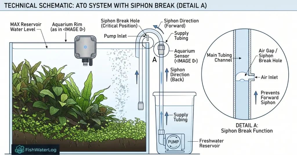
To effectively prevent ATO siphon crash fish tank disasters, technicians integrate a mechanical siphon break into the plumbing line. A siphon relies entirely on an unbroken, continuous liquid column. Introducing atmospheric air directly into the line immediately collapses the vacuum, terminating unintended water movement:
- Drilling the Siphon Hole: Drill a 1 to 2 mm transverse hole directly into the delivery tubing just above the pump.
- Crucial Placement: Ensure this hole is situated inside the reservoir and strictly above the highest possible water level of the container.
- Operational Flow: While the pump is active, a tiny spray of water diverts harmlessly back into the container while the main flow travels up to the tank.
- Instant Vacuum Rupture: When the controller powers down the pump, air is drawn through the hole, instantly breaking the fluid tension and halting all siphon action.
- Secondary Air Gap Defense: Always secure the delivery output nozzle slightly above the aquarium’s high-water mark so the tube end never sits submerged, preventing back-siphoning under all conditions.
Evaporation is a continuous thermodynamic process influenced by ambient atmospheric humidity, surface area, and thermal differentials, as documented by the USGS Water Science School.
Maintenance Protocols and Lifecycle Management
The long-term reliability and operational accuracy of an aquarium auto top off setup depend directly on regular, documented maintenance cadences. Treating automation as a “set and forget” system remains the primary cause of hardware failure and sensor calibration drift.
Optical Sensor Servicing and Descaling
In planted and biotope aquariums, optical sensors face continuous biological and chemical exposure:
- Biofilm and Mineral Accumulation: Over time, bacterial films, algae, and calcium carbonate scale form across the clear prism, altering its refractive index and impairing the sensor’s ability to distinguish between air and water.
- Monthly Chemical Cleaning: Extract and service optical sensors monthly. Soak the prism assembly briefly in a mild organic acid solution (such as 10% citric acid or standard white vinegar) to dissolve mineral crusts and organic slime safely.
- Non-Abrasive Handling: Never clean optical components with wire brushes, scouring pads, or abrasive sponges; microscopic scratches on the optical polymer permanently scatter infrared light beams and distort sensor readings. Wipe the prism face gently with a soft microfiber cloth instead.
Supply Pump Inspection and Descaling
Submersible centrifugal pumps used for top-off delivery require semi-annual mechanical inspection to prevent head loss and motor stalling:
- Impeller Well Maintenance: Detritus and mineral scale collect inside the magnetic impeller well over time, creating friction against the rotor, causing audible buzzing, and lowering output flow.
- Preserving Run-Time Baseline: Soaking and descaling the impeller assembly every six months maintains standard pump velocity, ensuring flow rates match the controller’s programmed baseline and algorithmic safety shut-offs function properly.
- Tubing and Siphon Check: Inspect the delivery line and verified siphon break hole for algal clogging to maintain free air intake and prevent ATO siphon crash fish tank failure modes.
Automated dosing and fluid replenishment operate most effectively alongside broader system care; ensure your overall routine is balanced by following our Mastering Fish Tank Care: The Complete Aquatic Habitat Guide. Practicing consistent hardware servicing ensures your automated system maintains long-term salinity stability freshwater parameters and protects pure ro di top off aquarium water delivery.
Routine Maintenance & Troubleshooting Checklist
| Issue / Symptom | Root Cause | Corrective Action |
|---|---|---|
| ATO pump runs continuously | Biofilm/algae covering optical prism | Wipe optical sensor with 10% citric acid or pure vinegar. |
| Rapid clicking / On-Off cycle | Surface wave turbulence | Relocate sensor away from filter outtakes; install a wave-guard baffle. |
| Pumping noise but no water flow | Air-lock in micro DC pump | Submerge and gently tilt pump underwater to release trapped air pocket. |
Conclusion
Transitioning a freshwater aquarium to an automated hydro-mechanical matrix resolves the persistent dangers of osmotic stress, parameter swings, and water chemistry drift. The deployment of a dedicated aquarium auto top off setup fundamentally elevates the standard of care, ensuring that vital solute concentrations and physical fluid volumes remain statically bound to safe, optimal parameters. Mastering how to install ATO on freshwater tank hardware allows hobbyists to automate daily top-offs while maintaining the precise salinity stability freshwater species require.
However, the integration of automation mandates a commensurate increase in engineering vigilance. Advanced solid-state telemetry does not replace the necessity of physical hydraulic safeguards. By engineering a foolproof siphon break to reliably prevent ATO siphon crash fish tank disasters and utilizing exclusively pure ro di top off aquarium water, the aquarist guarantees a resilient, stable ecosystem. This strategic implementation insulates the aquatic habitat against both environmental fluctuations and human oversight, establishing the setup as an exercise in rigorous aquatic engineering.
Frequently Asked Questions
What is the fundamental physiological purpose of an ATO in a freshwater aquarium?
An ATO replenishes water lost exclusively to atmospheric evaporation. Because dissolved minerals do not evaporate, this automated replacement maintains stable concentrations of Total Dissolved Solids (TDS) and general hardness, preventing osmotic shock to fish osmoregulatory systems.
Can municipal tap water be utilized in the ATO reservoir?
It is strongly advised against. Tap water contains baseline minerals, heavy metals, and chloramines. Using it for evaporation top-offs causes total dissolved solids and hardness to compound over time. A dedicated RO/DI water supply is the industry standard.
How do I clean optical water level sensors to ensure telemetry accuracy?
Wipe sensors gently with a non-abrasive microfiber cloth and soak them briefly in a mild citric acid or white vinegar solution to dissolve mineral crusts and biofilm without scratching the optical prism.
Why does my ATO pump continue to push water even after the controller turns it off?
This indicates a forward siphon. If the reservoir’s water level is higher than the outlet tube in the tank, gravity sustains fluid flow. You must install a siphon break hole in the delivery tubing above the reservoir water line to allow air in and collapse the vacuum.
Where is the optimal, hydrodynamically stable location to mount the primary water level sensor?
The sensor must be installed where evaporation actively drops the water line. In standalone tanks, this is inside the main display. In sump-filtered systems, it must be mounted exclusively in the sump’s return pump chamber.

1 thought on “Aquarium Auto Top Off Setup: Stop TDS Creep & Floods (2026)”