
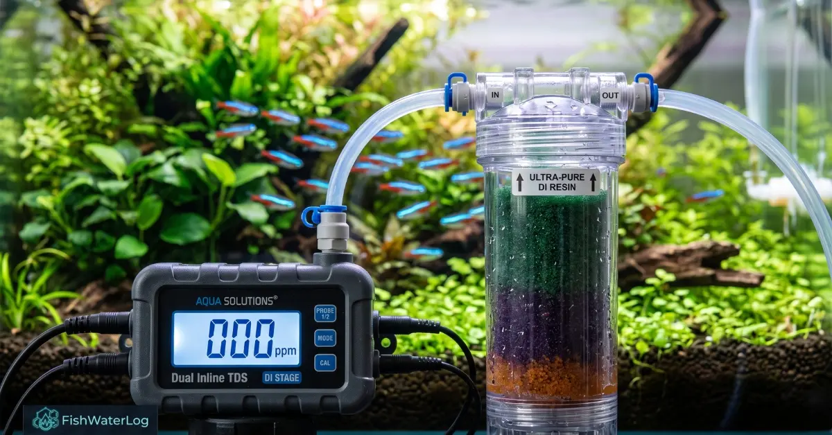
In the discipline of advanced aquatic husbandry—ranging from heavily planted high-tech freshwater biotopes to highly sensitive Caridina shrimp breeding facilities—the foundational requirement for long-term ecological success is absolute, uncompromising control over water chemistry. Municipal tap water contains an unpredictable matrix of heavy metals, chloramines, silicates, and carbonates. To recreate pristine natural environments, aquarists rely on Reverse Osmosis and Deionization (RO/DI) systems to strip source water down to pure H2O, establishing a sterile foundation for calculated remineralization. Proper biological filtration and water parameter stability are just as crucial as foundational fish tank care for your aquatic setup.
Achieving sustained permeate water purity, however, presents a continuous mechanical and chemical challenge. The most insidious obstacle in high-purity filtration is tds creep in aquarium ro di systems. This physiochemical occurrence degrades initial product water during startup by introducing a concentrated spike of Total Dissolved Solids directly into the downstream stages. Left unmanaged, it causes rapid deionization resin exhaustion and exposes livestock to hazardous solute swings. Controlled bench testing on a standard 75 GPD system highlights this curve: upon opening the supply valve against a closed auto-shutoff, permeate output registered an immediate 48 ppm spike across the initial 30 seconds of flow before steadily decaying to a stabilized baseline of 2 ppm after 120 seconds of sustained line pressure.
Implementing engineered protocols for preventing tds creep in aquarium ro systems is essential to protect both hardware efficiency and biological stability. Calibrating the correct ro membrane flush valve flush time clears stagnant startup solutes before water reaches the resin. Furthermore, real-time telemetry must account for conductivity sensor drift to ensure accurate measurement. Once purified, reconstituting the water with dedicated gh kh remineralization salts serves as the primary mechanism for osmotic shock prevention freshwater fish require to maintain stable osmoregulation and cellular integrity. Grounding filtration protocols in rigorous aquatic science research ensures livestock safety and long-term water parameter stability.
Table of Contents
The Thermodynamics and Physics of Reverse Osmosis
To fully comprehend the root causes of membrane contamination, one must first analyze the fundamental physics governing Thin-Film Composite (TFC) reverse osmosis systems. Standard osmosis is a passive thermodynamic process driven by the second law of thermodynamics, which favors maximum entropy. When two aqueous solutions of differing solute concentrations are separated by a semi-permeable membrane, solvent water molecules naturally migrate from the region of low solute concentration to the region of high solute concentration to achieve chemical and thermodynamic equilibrium.
The force driving this natural migration is known as osmotic pressure (Pi), mathematically defined by the Van ‘t Hoff equation:
Pi = iMRT.
Where:
- i represents the dimensionless Van ‘t Hoff index, accounting for the dissociation of solute particles.
- M represents the molar concentration of the solute within the solution.
- R represents the ideal gas constant.
- T represents the absolute temperature measured in Kelvin.
Hydrostatic Pressure and Membrane Flux Dynamics
In an active, pressurized filtration unit, booster pumps apply high hydrostatic pressure (Delta P) to source water on the intake brine side.
- Pressure Requirements: For reverse osmosis to proceed, applied hydrostatic pressure must vastly exceed the natural osmotic pressure (Delta P > Delta Pi).
- Selective Permeation: This mechanical force crushes water molecules through microscopic pores of the polyamide membrane, leaving rejected salts, heavy metals, and silicates behind in the boundary layer to be flushed.
- Purified Output: The fluid emerging post-membrane yields high-grade permeate water purity, stripping 95% to 99% of dissolved baseline ions.
- System Shutdown Dynamics: The structural integrity of this filtration barrier depends entirely on uninterrupted forward pressure; the instant that pressure drops, system thermodynamics invert.
The Chemical Mechanics of TDS Creep in Aquarium RO DI
The phenomenon of tds creep in aquarium ro di systems is an unavoidable consequence of thermodynamic equilibrium re-establishing itself the moment a filtration unit sits idle. When system pressure drops to zero—whether triggered manually or via automated Auto Top-Off (ATO) float switches—active reverse filtration immediately reverts to passive forward osmosis.
During idle downtime, the membrane canister houses two contrasting fluid environments separated only by the thin polyamide film:
- The Brine Side (Pre-Membrane): Highly concentrated waste fluid dense with rejected minerals, heavy metals, and carbonates elevated by concentration polarization.
- The Permeate Side (Post-Membrane): Aggressive, ultra-pure water with near-zero ion saturation that acts as a strong solvent seeking chemical stability.
Ionic Migration and Startup Contamination Spikes
Without continuous hydrostatic forward drive, thermodynamic forces equalize the barrier:
- Solute ions from the brine side slowly diffuse across the polyamide layer into the center permeate collection tube.
- Pure water molecules from the permeate side osmotically migrate backward to dilute concentrated brine.
- Over extended downtime, stagnant water sitting in the housing becomes heavily salinized.
- Upon restart, this stagnant surge bypasses initial filtration, causing inline digital meters to register high spikes (50 to 150+ ppm) before stabilizing.
Differentiating between normal startup behavior and physical hardware failure relies on a strict time metric: transient TDS creep naturally drops to a stable baseline (typically 2 to 6 ppm) within 30 to 60 seconds of sustained line pressure, whereas a reading that remains stubbornly high after several minutes of continuous production indicates a ruptured polyamide membrane, bypassed internal O-rings, or depleted pre-filtration stages.
The Cascade Effect: Deionization Resin Exhaustion
The primary casualty of unmanaged startup spikes falls on the final polishing stage: the mixed-bed deionization (DI) resin. While the RO membrane removes the vast majority of minerals, the DI resin uses ion-exchange chromatography to bind remaining trace ions down to an absolute 0 ppm baseline. While mechanical and biological filtration trap debris and process nitrogenous waste, specialized filter media like mixed-bed ion-exchange resin is required to achieve true zero-conductivity polish.
Mixed-bed DI resin consists of porous polymer beads manufactured with reactive functional sites:
- Cation Exchange Resin: Strong acid functional groups (such as sulfonic acid) exchange dissolved cations (Ca2+, Na+, Cu2+) for hydrogen ions (H+).
- Anion Exchange Resin: Strong base functional groups (such as quaternary ammonium) exchange dissolved anions (Cl-, SO4 2-, SiO3 2-) for hydroxyl ions (OH-).
- Water Molecule Formation: The released H+ and OH- ions immediately bind to form pure, stable H2O.
Pro-Tip on Source Water CO2: If DI resin exhausts rapidly despite flushing TDS creep, test your RO permeate for dissolved CO2 using an aquarium alkalinity/pH titration test. Dissolved carbon dioxide passes freely through RO membranes as gas, binding aggressively to anion resin beads without showing on inline TDS meters.
Finite Bed Capacity and Selective Ion Dumping
- Accelerated Depletion: Because functional sites have a mathematically fixed capacity, repeatedly absorbing 70 to 100 ppm startup spikes causes rapid, premature deionization resin exhaustion.
- Silicate and Phosphate Breakthrough: As media nears exhaustion, resin selectively releases weakly bound ions (specifically silicates and phosphates) into product water to bind higher-affinity ions.
- Algal Consequences: These unmonitored silicates bypass the barrier and trigger aggressive diatom and filamentous algae blooms in the main display system.
Table: DI Resin Depletion Rate Comparison
| Input TDS to DI Stage | Cause of Input Level | Expected Resin Lifespan (per 10-inch cartridge) | Economic Efficiency |
|---|---|---|---|
| 0–2 ppm | Ideal RO function; flush valve utilized | ~500+ Gallons | Optimal / Highly Efficient |
| 5–10 ppm | Standard RO function; no flush protocol | ~150 – 200 Gallons | Moderate |
| 30–50 ppm | Frequent short-cycling; TDS creep absorbed | ~30 – 50 Gallons | Extremely Inefficient |
| 70+ ppm | Severe TDS creep; compromised membrane | < 15 Gallons | Critical Failure |
Engineering Interventions: Preventing TDS Creep in Aquarium RO Systems
Mitigating the destructive effects of solute spikes is not merely a matter of purchasing “better” or “premium” filter cartridges; it requires a structural and mechanical modification to the fluid mechanics of the filtration unit itself. The primary objective of preventing tds creep in aquarium ro systems is physically isolating the initial concentrated water burst away from the polishing stages before it can cause premature deionization resin exhaustion.
The Misconception of the Standard Waste-Line Flush Valve
A widespread misconception within the aquatic husbandry community is that installing a standard, factory-provided flush kit eliminates the solute spike.
- Mechanical Function: A standard flush valve is plumbed as a bypass loop parallel to the capillary flow restrictor on the brine line. Opening this valve drops system backpressure to near zero, increasing cross-flow velocity across the membrane surface to scrub away calcium scale, organic fouling, and particulate matter.
- Permeate Isolation Failure: While this maintenance step extends membrane longevity, it does nothing to prevent tds creep in aquarium ro di systems. Solute migration occurs directly on the product side within the center collection tube. Rinsing the exterior waste channel leaves stagnant, salinized fluid untouched, which pushes into the resin bed once production resumes.
The True Engineering Solution: The Permeate Diverter Valve
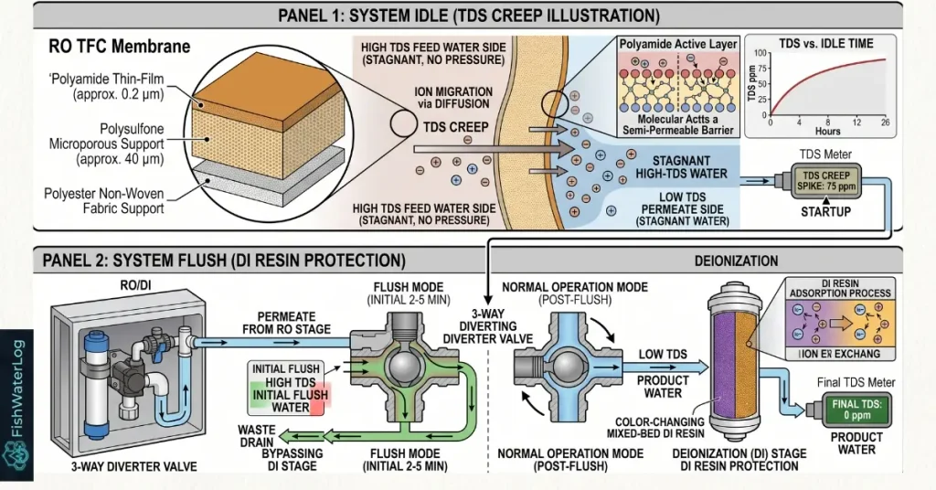
To guarantee long-term permeate water purity, filtration setups require a dedicated post-membrane diversion line. This configuration positions a 3-way diverter valve (manual ball valve or electronic solenoid) directly on the 1/4-inch tubing between the RO membrane output and the DI canister intake.
Standard Operational Protocol for the Bypass Valve:
- Pre-Startup Configuration: Before applying line pressure or powering on the booster pump, position the diverter valve to the bypass or drain line.
- Purging the Creep: Engage the RO system. The initial concentrated burst exits the housing and diverts straight to the drain, completely bypassing the DI resin canister.
- Analytical Telemetry: Monitor an inline digital TDS meter plumbed on the post-RO line to track real-time concentration drops. Verifying sensor readings also ensures that operational issues are not masked by conductivity sensor drift.
- Resuming Production: Once the reading stabilizes at the baseline rejection level (typically 2 to 4 ppm), switch the valve back to the production position to route verified water through the DI stage.
This baseline permeate can then be treated with specialized gh kh remineralization salts, ensuring targeted mineral ratios for reliable osmotic shock prevention freshwater fish require in delicate aquatic environments.
Determining the Optimal RO Membrane Flush Valve Flush Time
The mechanical efficiency of a DI bypass loop relies entirely on the precise duration of the purge cycle. If terminated prematurely, concentrated ionic spikes breach the polishing stage and trigger rapid deionization resin exhaustion. Conversely, an excessively long purge needlessly dumps purified water down the drain, reducing overall recovery efficiency.
Establishing the optimal ro membrane flush valve flush time requires evaluating line pressure, flow dynamics, and the membrane’s rated Gallons Per Day (GPD) capacity.
System Sizing and Flush Duration Dynamics
- Standard Systems (50–75 GPD at 65–75 PSI): Fluid dynamic modeling confirms that an initial purge of 30 to 60 seconds sufficiently displaces the stagnant, mineralized volume held within the center collection tube. This rapid purge shields downstream media from tds creep in aquarium ro di startups.
- High-Capacity or Low-Pressure Setups (150+ GPD or <50 PSI): Suboptimal line pressure and larger internal housing volumes reduce linear flow velocity, extending the required ro membrane flush valve flush time to 90–120 seconds for comprehensive clearing.
- Automation Integration: For automated systems, programming this specific purge delay into a latching relay actively supports preventing tds creep in aquarium ro systems caused by frequent cycle starts.
Inline Telemetry Verification
Rather than depending on a static timer, operators should use dual inline digital conductivity probes to monitor real-time membrane effluent:
- Concentration Decay Tracking: Startup readings typically spike high before dropping rapidly along an asymptotic dilution curve.
- Sensor Accuracy Protocols: Probes must be maintained regularly against conductivity sensor drift to prevent false diagnostics caused by micro-bubble entrapment or electrode scaling.
- Engaging Polishing Stages: Switch the diverter valve to the DI canister only when inline telemetry confirms steady baseline permeate water purity (typically 2 to 4 ppm).
Purging startup solutes guarantees pristine zero-TDS effluent, allowing calculated additions of gh kh remineralization salts to provide the exact osmotic balance needed for reliable osmotic shock prevention freshwater fish require.
System Automation and the Dangers of Short-Cycling
The manual bypass method functions well for batch-producing water in holding reservoirs, but automated configurations face unique thermodynamic hazards. In automated setups, Auto Top-Off (ATO) optical sensors or mechanical float valves detect minor evaporation in the sump and cycle the filtration system on to deliver micro-bursts of replacement water.
Direct-plumbing an RO/DI unit to an aquarium sump using a simple mechanical float valve creates a destructive operational pattern known as “micro-cycling” or “sipping,” where the system initiates dozens of short, two-minute runs per day in response to surface evaporation; because the membrane never operates long enough to clear its transient startup spike, the mixed-bed deionization resin is continuously bombarded with concentrated creep water, exhausting expensive media beds in a matter of weeks rather than months.
The Destructive Dynamics of Short-Cycling
- Frequent Activation Spikes: If a large system evaporates one gallon daily, an unbuffered sensor triggers the unit 20 to 30 times over a 24-hour window, producing mere ounces per cycle.
- Accelerated Resin Consumption: Because ionic migration occurs during every idle period, this cycling subjects polishing media to dozens of startup bursts daily, making short-cycling the primary cause of rapid deionization resin exhaustion.
- Permeate Degradation: Absorbing continuous bursts of tds creep in aquarium ro di units saturates reactive polymer sites without delivering enough continuous pure water to offset the chemical load.
- Sensor Inaccuracies: Frequent cycling can trap micro-cavitation bubbles against analytical probes, aggravating conductivity sensor drift and presenting false diagnostic spikes.
Engineering Solutions for Automated Systems
Implementing engineered automation protocols is critical for preventing tds creep in aquarium ro systems:
- Hysteresis Dual-Sensor Control: Rather than reacting to millimeter-level drops, programmable controllers utilize paired high and low optical sensors inside a secondary reservoir. The system remains completely powered down until water reaches the lower sensor, triggering a single continuous production run of several hours until the high sensor trips. Learn how to properly configure your aquarium auto top off setup with dual optical sensors to prevent destructive short-cycling.
- Automated Bypass Solenoids: Combining hysteresis logic with an automated, normally closed solenoid valve purges startup fluid to a drain. Programming an exact ro membrane flush valve flush time of 60 seconds diverts the initial surge, switching to the DI bed only when output stabilizes.
- Sustained Permeate Quality: Managing production cycles ensures consistent baseline permeate water purity, preventing trace silicates and heavy metals from breaking through into top-off reservoirs.
- Stable Post-Filtration Dosing: Pure, uncompromised product water allows reliable dosing with gh kh remineralization salts, providing the exact osmotic stability needed for osmotic shock prevention freshwater fish require during scheduled water changes.
Aquatic Physiology: Osmotic Shock Prevention Freshwater Fish
Maintaining absolute permeate water purity through disciplined filtration management is an essential biological necessity for livestock health. While RO/DI systems eliminate hazardous tap toxins, unmineralized H2O is biologically sterile and aggressively hypotonic. Introducing living organisms directly into raw product water—or exposing them to erratic mineral spikes caused by tds creep in aquarium ro di systems breaching exhausted resin—triggers severe physiological collapse.
Teleost Osmoregulation and Hyperosmotic Dynamics
Freshwater fish are naturally hyperosmotic relative to their surrounding environment. The concentration of internal salts, electrolytes, and blood plasma solutes is significantly higher than that of ambient water. Because water naturally migrates across semi-permeable boundaries to reach chemical equilibrium, water continuously diffuses inward through vascularized gill membranes and epithelial layers. To keep sensitive inhabitants healthy, always monitor the latest husbandry trends in aquarium fish care and environmental management.
To survive this continuous osmotic influx, freshwater fish rely on hormone-regulated physiological adaptations:
- Renal Fluid Clearance: The kidneys process and excrete massive, continuous amounts of dilute urine to purge excess fluid from internal tissues.
- Active Ionocyte Transport: Specialized mitochondria-rich cells (chloride cells) in the gill epithelium consume ATP to actively pump multivalent ions—principally calcium, sodium, magnesium, and chloride—into the bloodstream against steep concentration gradients. Detailed studies on teleost osmoregulation and cellular physiology can be explored further at the Journal of Fish Biology.
The Etiology of Osmotic Shock and Systemic Collapse
Exposing fish to raw effluent devoid of essential minerals creates an impossibly steep osmotic gradient. The fish’s chloride cells fire rapidly but find zero available ions, resulting in acute physical degradation:
- Cellular Edema and Hemolysis: Water rushes into cellular spaces unchecked, causing severe tissue swelling and the widespread lysis (bursting) of erythrocytes (red blood cells).
- Systemic Hyponatremia: Rapid dilution of blood plasma sodium triggers neuromuscular failure, externally visible through clamped fins, extreme lethargy, buoyancy loss, and erratic spiraling behaviors.
- Gill Hyperplasia and Hypoxia: Epithelial gill cells thicken pathologically to halt inward water migration, permanently compromising respiratory gas exchange and suffocating the fish.
- Invertebrate Cellular Lysis and Ecdysis Failure: Unlike teleost fish, freshwater dwarf shrimp (Neocaridina davidi) lack complex renal osmoregulatory systems, leaving them acutely vulnerable to osmotic shock; exposure to pure, un-remineralized RO water forces violent fluid influx causing cellular lysis, while sudden TDS and general hardness (GH) swings disrupt post-molt calcium absorption, triggering fatal incomplete shell shedding known as the “White Ring of Death”.
Reconstitution Safeguards for Livestock Stability
Mitigating this pathology requires strict osmotic shock prevention freshwater fish protocols supported by mechanical and chemical interventions:
- Hardware Protection: Implementing engineered solutions for preventing tds creep in aquarium ro systems ensures baseline water remains genuine zero-TDS.
- Flush Valve Calibration: Adhering to a verified ro membrane flush valve flush time prevents startup spikes from causing premature deionization resin exhaustion.
- Sensor Accuracy: Routine maintenance prevents conductivity sensor drift from giving false conductivity readouts.
- Mineral Reconstitution: Base permeate must always be rebalanced using calculated gh kh remineralization salts before reaching livestock, establishing the precise mineral profile necessary to protect teleost cellular integrity.
Nitrifying Biofilter Shock: Sudden osmotic swings and carbonate starvation caused by unbuffered or fluctuating RO/DI effluent severely impair nitrifying bacterial kinetics, stalling ammonia oxidation and risking secondary toxic nitrogen spikes across the biological filter.
Post-Filtration Reconstitution: GH KH Remineralization Salts
To guarantee absolute osmotic shock prevention freshwater fish safety, pure RO/DI water must never be introduced directly into an active aquarium ecosystem. Once the product effluent is verified at 0 ppm TDS via proper membrane flushing and DI polishing, it must be methodically reconstituted using specialized gh kh remineralization salts to recreate the precise hydrochemical profile of the intended biotope.
Water Hardness Chemistry: GH vs. KH Mechanics
Water hardness in high-purity aquatic systems is governed by two distinct chemical parameters:
- General Hardness (GH): Measures the concentration of multivalent cations, primarily calcium (Ca2+) and magnesium (Mg2+). These essential electrolytes drive teleost branchial osmoregulation, skeletal calcification, muscular function, and invertebrate molting kinetics.
- Carbonate Hardness (KH): Quantifies the water’s acid-neutralizing buffering capacity (alkalinity), composed mainly of bicarbonate (HCO3-) and carbonate (CO3 2-) anions. KH acts as a sacrificial chemical buffer against organic nitric acids produced by nitrifying bacteria, preventing sudden pH crashes.
Stoichiometric Mineral Ratios for Biotope Targeting
High-grade gh kh remineralization salts utilize specific physiological ratios—typically 3:1 or 4:1 calcium-to-magnesium using pharmaceutical compounds such as calcium sulfate and magnesium chloride—to replicate pristine lacustrine and riverine chemistries.
- Softwater Husbandry: For delicate species like wild Amazonian Discus, Cardinal Tetras, or Caridina cantonensis shrimp, aquarists target low environmental conductivity. Reconstituting pristine 0 ppm water to a controlled 100–120 ppm TDS supplies sufficient divalent cations for ionocyte function while keeping KH minimal to maintain an acidic pH. Targeting exact mineral ratios is essential when calibrating cherry shrimp water parameters for optimal molting and survival.
- High-Purity Baseline Precision: Effective protocols for preventing tds creep in aquarium ro systems ensure that foundation water is genuinely zero-TDS. This chemical purity guarantees that salt dosage calculations remain mathematically exact.
- Contaminant Breakthrough Hazards: If tds creep in aquarium ro di startups are allowed to cause premature deionization resin exhaustion, unmonitored municipal silicates and copper bypass into the storage water. This invalidates remineralization calculations and reintroduces severe osmotic stress to livestock.
- Telemetry Calibration: Always ensure inline diagnostic probes are clear of conductivity sensor drift and run through an adequate ro membrane flush valve flush time before measuring final reconstituted batches to ensure sustained permeate water purity.
Advanced Diagnostics: Overcoming Conductivity Sensor Drift
A robust, fail-safe filtration protocol relies entirely on the precision of analytical telemetry gathered during daily operation. Inline digital TDS meters serve as the primary diagnostic monitors to assess membrane rejection health, confirm sustained permeate water purity, and calculate bypass purge cycles. These instruments operate by passing an electrical current between two titanium or stainless-steel electrodes positioned directly within the water column. Because ultra-pure water is an electrical insulator, dissolved ionic compounds increase conductivity. The device measures electrical conductivity (EC) in micro-Siemens per centimeter (uS/cm) and applies a programmed conversion factor (typically 0.5 based on standard NaCl solutions) to display Total Dissolved Solids in parts per million (ppm).
However, these precision probes are susceptible to conductivity sensor drift, leading to inaccurate system diagnostics and costly operator errors. An aquarist dealing with drifting telemetry might misinterpret baseline readings, prematurely discard functional media, or fail to recognize true membrane tears.
Etiology of Diagnostic Inaccuracies
- Electrode Biofouling and Mineral Scaling: Microscopic organic biofilms form over probe tips, while stagnant, hard source water precipitates calcium carbonate scale over the metal pins. This accumulation artificially increases electrical resistance across the sensor gap, producing falsely depressed TDS readings that dangerously mask breakthrough contaminants.
- Cavitation and Micro-Bubble Accumulation: High-velocity water traversing microscopic membrane pores generates dissolved gas cavitation. Microscopic bubbles adhere tightly to the titanium pins, disrupting current flow and causing erratic, jumping numbers that mimic the appearance of true tds creep in aquarium ro di spikes.
- Thermal Lag and Temperature Fluctuations: Electrical conductivity increases by approximately 2% for every 1°C increase in temperature. While modern meters utilize Automatic Temperature Compensation (ATC), thermal lag in built-in thermistors leads to skewed readings during sharp seasonal shifts in municipal tap temperature.
- Galvanic Polarization: Continuous direct current (DC) applied across hobbyist-grade pins causes dissolved ions to migrate toward oppositely charged electrodes, creating a polarized plating layer that skews calibration over time.
- Defective Permeate Check Valve & ASOV Creep: A cracked internal rubber seat in the 1/4-inch permeate check valve or a torn diaphragm in the mechanical Auto Shut-Off Valve (ASOV) allows high-pressure concentrate brine to continuously bleed backward into the permeate collection tube during idle periods, generating continuous, un-clearable TDS spikes.
Mitigation and Calibration Strategies
Maintaining analytical precision is essential for verifying when the ro membrane flush valve flush time has successfully cleared startup solutes before directing product water to the resin. Similar to the precision required during aquarium probe calibration for redox sensors, inline TDS electrodes demand routine descaling and realignment to eliminate drift.
- Chemical Acid Descaling: Regularly remove sensor probes from their quick-connect T-fittings and submerge them in a mild acidic bath, such as diluted white vinegar. This safely dissolves calcium scale and strips organic biofilm without abrading or scratching sensitive titanium surfaces.
- Laboratory Standard Calibration: Calibrate digital meters on a strict monthly schedule using certified 342 ppm NaCl standard reference solutions to realign processing algorithms with true electrical conductivities. For comprehensive industry standards on membrane physics and water chemistry diagnostics, consult the official guidelines provided by the Water Quality Association.
- Flush Validation: Verified telemetry allows operators to confirm the effectiveness of hardware systems built for preventing tds creep in aquarium ro systems, ensuring that media beds avoid premature deionization resin exhaustion.
- Reconstitution Integrity: Reliable 0 ppm effluent guarantees that post-filtration dosing using balanced gh kh remineralization salts produces the exact parameters required for osmotic shock prevention freshwater fish depend upon for cellular stability.
Overlooked Variables in RO/DI Management
While standard aquatic husbandry literature routinely covers basic sediment pre-filter replacement schedules and color shifts in indicating media, critical knowledge gaps remain regarding high-purity fluid mechanics. Many platforms advocate for generic rules like “flushing the membrane” but fail to distinguish between brine-side surface cleaning and product-line solute purging.
The Pre-Flush vs. Post-Flush Paradigm
Standard operating procedures focus primarily on flushing the waste line after a production run has ended.
- Limitations of Post-Flushing: A post-production waste flush clears concentrated brine to reduce boundary-layer polarization before shutdown. While this slightly depresses the concentration gradient, it cannot overcome the laws of thermodynamics; passive ionic diffusion across the polyamide film continues unabated during extended downtime.
- The Pre-Production Bypass Imperative: The primary missing link in high-purity water management is executing an active pre-production bypass. Diverting the initial product burst straight to a drain for an optimized ro membrane flush valve flush time of 60 seconds before it contacts the media bed is exponentially more effective at preventing deionization resin exhaustion than any post-production cleaning cycle.
Mechanical Misconceptions and Systemic Solutions
- Ineffectiveness of Permeate Check Valves: Many aquarists install simple check valves on the permeate line assuming they arrest solute migration. While spring-loaded check valves stop pressurized reservoir backflow, they do nothing to halt localized ionic equilibrium seeking across the microscopic pores of the membrane barrier.
- Pressurized Storage Tank Degradation: Utilizing under-sink pressurized bladder tanks dramatically increases TDS creep. As internal bladder backpressure builds, the net driving pressure across the membrane plummets, reducing rejection efficiency and creating a continuous volume of elevated-TDS water that instantly exhausts downstream DI cartridges if tapped directly.
- Eliminating Auto Top-Off Cycling: Upgrading automated top-off systems with dual-level hysteresis controllers prevents destructive micro-bursts, addressing one of the leading causes of tds creep in aquarium ro di setups.
- Sensor Verification: Operators must periodically clean and calibrate diagnostic probes to eliminate conductivity sensor drift, ensuring that inline telemetry accurately reflects true effluent purity.
- Engineered Systems Management: Transitioning from reactive maintenance to an engineered approach for preventing tds creep in aquarium ro systems locks in consistent permeate water purity. This stable, zero-conductivity base ensures that post-filtration dosing with balanced gh kh remineralization salts remains mathematically precise, providing reliable osmotic shock prevention freshwater fish require for lifelong cellular integrity.
Conclusion
The successful construction and long-term management of highly sensitive aquatic ecosystems demands a rigorous, uncompromising, and scientifically grounded approach to water chemistry. The phenomenon of tds creep in aquarium ro di systems represents a hidden yet highly destructive mechanical variable that undermines the fundamental purpose of advanced water filtration. Driven by natural osmotic migration during periods of system inactivity, stagnant solutes breach the membrane barrier, directly resulting in rapid, costly deionization resin exhaustion and severely compromising permeate water purity. Relying solely on factory-supplied waste-line flush kits is an incomplete and fundamentally flawed solution for protecting product water. True stability requires implementing hardware solutions for preventing tds creep in aquarium ro systems through a product-line bypass valve, carefully calibrated to an optimized ro membrane flush valve flush time to ensure all concentrated startup water is safely diverted away from delicate polishing stages.
Furthermore, accurately analyzing system performance requires constant vigilance against conductivity sensor drift through regular cleaning and chemical calibration of diagnostic equipment. Ultimately, mastering the mechanical filtration process is only the first step in successful husbandry. Understanding the delicate osmoregulatory mechanisms of teleost fish and invertebrates dictates that pure RO/DI water must be methodically treated with carefully calculated gh kh remineralization salts prior to use. Only through the synergetic combination of immaculate mechanical filtration, intelligent system automation to prevent short-cycling, and precise biochemical reconstitution can an aquarist guarantee effective osmotic shock prevention freshwater fish strategies, fostering a thriving, scientifically managed, and sustainable aquatic environment.
Frequently Asked Questions
Essential technical insights on reverse osmosis thermodynamics, sensor calibration, and livestock safety.
What exactly is the physical cause of TDS Creep? +
TDS (Total Dissolved Solids) Creep is the slow, thermodynamic diffusion of salts and minerals from the highly concentrated waste side of a reverse osmosis membrane to the purified product side while the RO/DI system is turned off and devoid of hydrostatic pressure[cite: 3]. When the unit restarts, this contaminated water creates a massive initial spike in the TDS output[cite: 3].
Will a standard factory flush kit stop TDS Creep? +
No[cite: 3]. A standard flush kit installed on the waste line only clears physical scale and organic buildup from the front face of the membrane[cite: 3]. Because TDS creep happens on the clean (permeate) side of the membrane, operators must install a separate 3-way diverter bypass valve between the RO membrane and the DI resin to shunt the initial high-TDS water directly to the drain[cite: 3].
How do I determine what my RO membrane flush valve flush time should be? +
For standard residential RO/DI units (50 to 100 GPD), an ro membrane flush valve flush time of 30 to 60 seconds is entirely sufficient to clear stagnant solute volumes before engaging the DI resin[cite: 3]. For lower pressure systems or higher capacity dual-membrane units, extend the flush to 90 to 120 seconds[cite: 3]. Always verify total clearance using a calibrated inline digital TDS meter[cite: 3].
Why is my mixed-bed DI resin changing color and exhausting so rapidly? +
Rapid deionization resin exhaustion occurs when polishing media absorbs concentrated startup TDS creep spikes every single time the system cycles on[cite: 3]. This depletion accelerates severely if the unit is connected directly to an Auto Top-Off (ATO) float valve that short-cycles multiple times a day for brief top-offs[cite: 3].
Can I use ultra-pure RO/DI water directly in my freshwater aquarium? +
Absolutely not[cite: 3]. Raw permeate water purity is completely devoid of multivalent minerals, meaning it has zero buffering capacity (KH) to stabilize pH and zero electrolytes (GH) for osmoregulation[cite: 3]. Placing livestock directly into pure RO/DI water creates severe hypotonic stress, cellular swelling, nervous system failure, and rapid mortality[cite: 3].
What is the proper method to prevent osmotic shock when performing water changes? +
To achieve effective osmotic shock prevention freshwater fish require, aquarists must reconstitute 0 ppm RO/DI water using balanced gh kh remineralization salts[cite: 3]. Ensure the newly reconstituted water matches both the temperature and target TDS parameters of the main display tank before slowly introducing it to livestock[cite: 3].
Why is my inline digital TDS meter jumping around erratically or showing falsely low numbers? +
Erratic or inaccurate readings are classic symptoms of conductivity sensor drift[cite: 3]. This is typically caused by micro-bubbles clinging to sensor pins, biological biofilms, or mineral scaling on the probe tips[cite: 3]. Remove the probes, clean them gently using a mild acidic bath like vinegar, and recalibrate using certified 342 ppm NaCl calibration fluid[cite: 3].

9 thoughts on “TDS Creep in Aquarium RO DI: Osmotic Shock Prevention Guide”